Dalian Eastern Display Co., Ltd.
Dalian Eastern Display Co., Ltd.


The Serial Peripheral Interface (SPI) bus is a synchronous, full-duplex communication protocol used extensively in embedded systems. A 4-wire SPI configuration utilizes four lines: MOSI (Master Out Slave In), MISO (Master In Slave In), SCK (Serial Clock), and CS (Chip Select). Understanding how these lines behave, especially during the termination or exit of a communication sequence, is crucial for robust system design. This article will delve into the various exit conditions you might encounter with a 4 wire spi interface exit and provide practical solutions for troubleshooting problems.
One of the most common reasons for a 4 wire spi interface exit problem is an unexpected de-assertion of the Chip Select (CS) line. This can occur due to software bugs, hardware glitches (e.g., noise on the CS line), or incorrect timing. If the CS line goes high prematurely, the SPI transaction might be terminated before the intended data transfer is complete. Properly managing the CS line in your software is essential. Consider using well-defined functions for asserting and de-asserting CS to avoid accidental premature de-assertions.
SPI communication relies on precise timing between the clock signal (SCK) and the data transfer. Incorrect clock frequency, glitches on the clock line, or insufficient setup/hold times can lead to data corruption or incomplete transactions, resulting in issues with the 4 wire spi interface exit. Using a logic analyzer to observe the signals on all four lines (MOSI, MISO, SCK, CS) is invaluable in identifying timing-related problems. Ensure that your hardware meets the specified timing requirements of the SPI device. Refer to the device datasheet for precise timing specifications.
Data corruption during SPI communication can result in unexpected behavior and problems with 4 wire spi interface exit. This could be due to noise on the data lines (MOSI/MISO), clock glitches, or faulty hardware. Implementing parity checks or CRC (Cyclic Redundancy Check) in your communication protocol can help detect and mitigate data corruption. Using differential signaling or other techniques to improve signal integrity is crucial in noisy environments. Additionally, double-checking your wiring and ensuring proper signal grounding can help reduce noise-induced issues.
Software bugs are a frequent cause of SPI problems. Errors in the SPI driver software, incorrect buffer handling, or race conditions can all lead to a premature 4 wire spi interface exit. Thorough software testing, including unit testing and integration testing, is essential to identify and resolve software-related issues. Debugging tools and logging mechanisms can provide crucial insights into the behavior of your SPI communication.
Effective troubleshooting involves a systematic approach. Here’s a suggested workflow:
To avoid problems with 4 wire spi interface exit, follow these best practices:
By understanding the common causes of 4 wire spi interface exit issues and employing effective troubleshooting techniques, you can significantly improve the reliability of your SPI communication. Remember that careful design, proper testing, and a systematic approach are key to success.
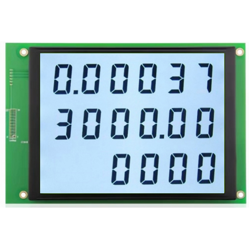
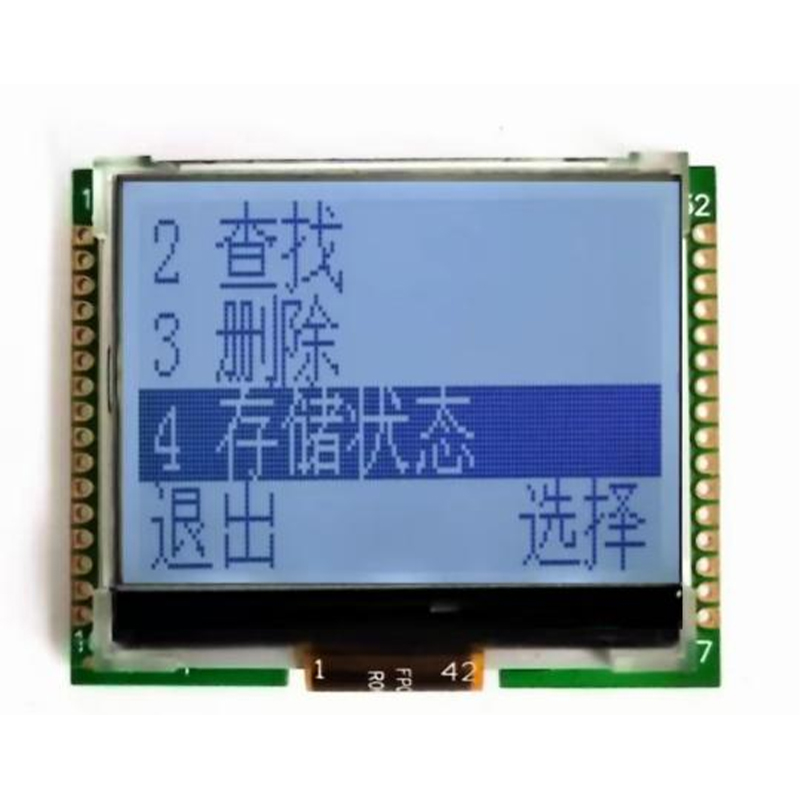
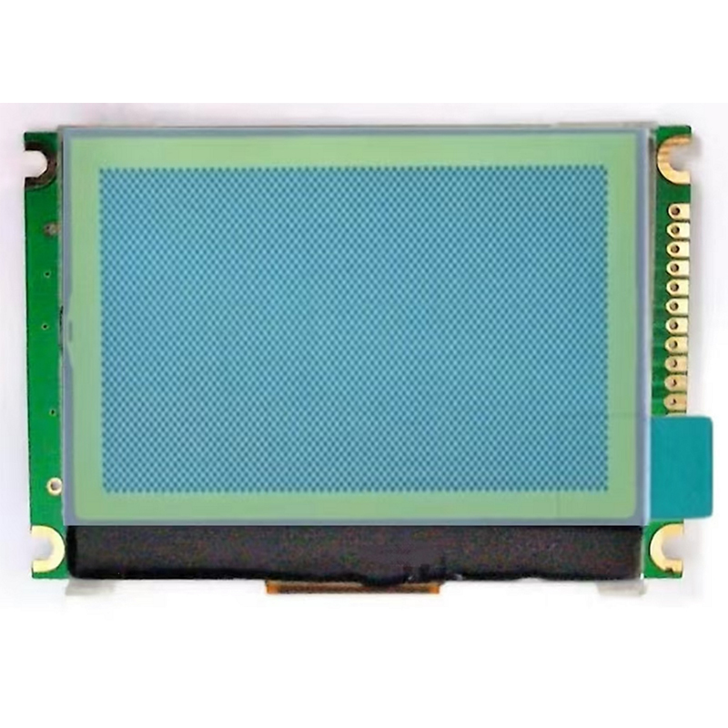
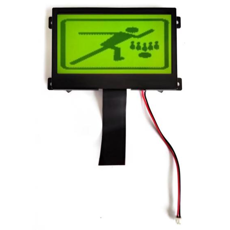
For high-quality LCD displays and other components which may utilize SPI interfaces, consider exploring the products offered by Dalian Eastern Display Co., Ltd.. They offer a wide range of solutions for various embedded system applications.