Dalian Eastern Display Co., Ltd.
Dalian Eastern Display Co., Ltd.


This guide provides a complete overview of using an 8x8 dot matrix display with an Arduino microcontroller. We'll cover everything from selecting the right display and connecting it to your Arduino, to writing code to display various text and images. Learn how to troubleshoot common issues and explore advanced techniques for maximizing your display's capabilities. Whether you're a beginner or experienced with electronics, this guide offers valuable insights and practical examples to help you succeed with your 8x8 dot matrix display Arduino product projects.
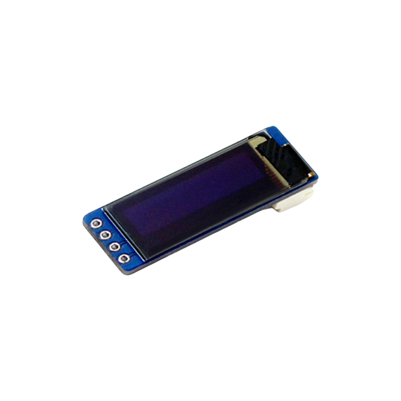
The market offers various 8x8 dot matrix display Arduino product options. Common types include common cathode and common anode displays. The choice depends on your specific needs and the capabilities of your Arduino. Consider factors like brightness, viewing angle, and power consumption. Many displays are available from various online retailers. Ensure you select a display compatible with your Arduino's voltage and pin configuration. For example, a common choice is the MAX7219-based display, known for its ease of use with Arduino. It simplifies controlling multiple digits or segments with fewer Arduino pins.
A key difference lies in how segments are illuminated. In a common cathode display, all the cathodes (negative terminals) are connected together, while each segment has its own anode (positive terminal). In a common anode display, it’s the reverse – all anodes are connected, and each segment has its own cathode. This difference impacts how you wire and program your display. Consult the datasheet of your chosen display to understand its specific configuration.
Connecting your 8x8 dot matrix display Arduino product involves connecting the display's pins to the corresponding pins on your Arduino board. This usually includes VCC (power), GND (ground), DIN (data in), CLK (clock), and CS (chip select) pins. Refer to the display's datasheet for precise pin assignments. Proper wiring is crucial to avoid damaging your components. Ensure you connect the power supply correctly and use appropriate jumper wires.
A typical wiring diagram for a MAX7219-based 8x8 dot matrix display Arduino product might look like this:
| Arduino Pin | Display Pin | Description |
|---|---|---|
| 5V | VCC | Power Supply |
| GND | GND | Ground |
| Digital Pin 2 | DIN | Data Input |
| Digital Pin 3 | CLK | Clock |
| Digital Pin 4 | CS | Chip Select |
Once connected, you can program your Arduino to control the display. The specific code will depend on the type of display you are using. Many libraries are available to simplify the process. For MAX7219-based displays, the Max7219 library is a popular choice. This library provides functions for displaying characters, numbers, and custom images.
This is a simplified example and may need adjustments based on your specific setup and library version.
#include Max7219 matrix = Max7219(2, 3, 4); //Pins for DIN, CLK, CSvoid setup() { matrix.begin();}void loop() { matrix.print(Hello); delay(2000);} Common problems include the display not lighting up, displaying incorrect characters, or flickering. Check your wiring, power supply, and code for errors. Make sure your libraries are correctly installed and that you're using the correct pin assignments. Consult online forums and communities for assistance if needed. Consider using a multimeter to test the voltage and current at different points in your circuit.
Beyond basic text display, 8x8 dot matrix display Arduino products can be used for various applications, including creating scrolling messages, displaying animations, building simple games, and even creating custom clock displays. Exploring these advanced applications greatly enhances the versatility of the display. Experiment with different graphics and animation techniques to unleash its creative potential. Check resources online for inspiration and code examples.
For high-quality 8x8 dot matrix displays and other LCD products, consider exploring Dalian Eastern Display Co., Ltd. They offer a wide range of options to suit your needs.