Dalian Eastern Display Co., Ltd.
Dalian Eastern Display Co., Ltd.


This guide provides a comprehensive overview of using Arduino with LED segment displays, covering everything from basic principles to advanced techniques. We’ll explore various display types, common libraries, and practical project examples, helping you to confidently integrate Arduino LED segment displays into your projects.
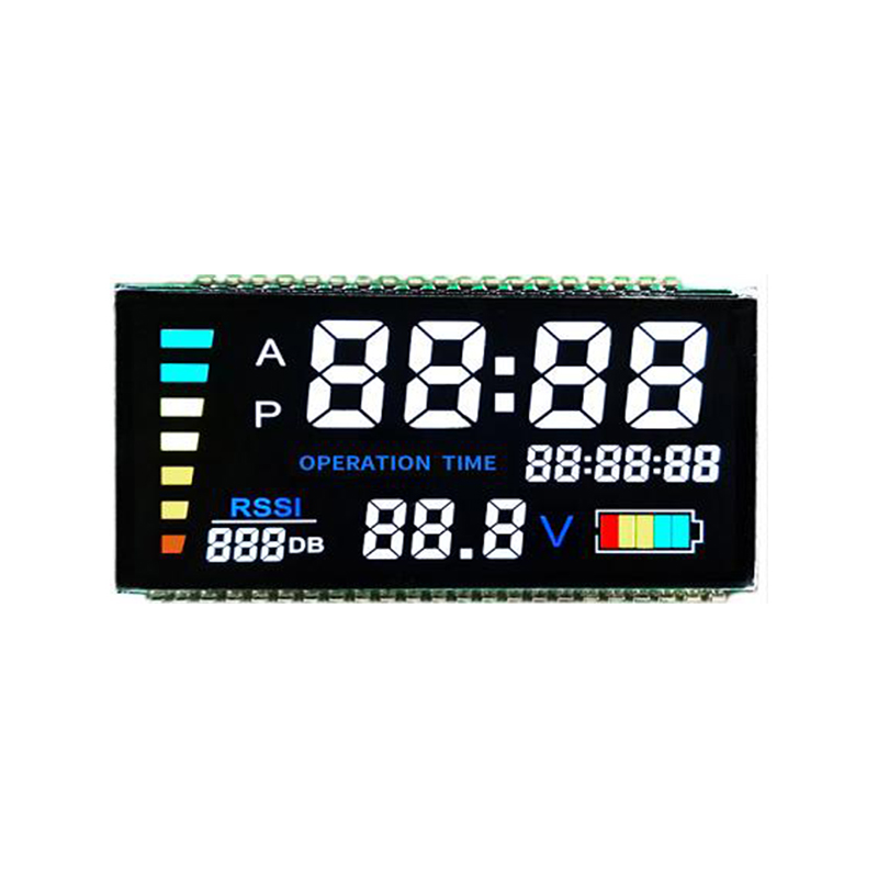
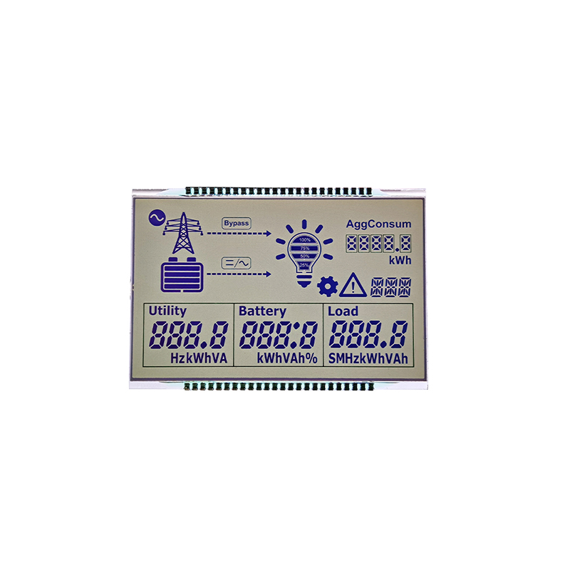
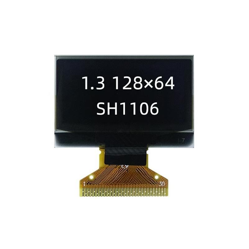
LED segment displays come in various sizes, configurations (common anode or common cathode), and levels of complexity. Common types include 7-segment, 8-segment (with a decimal point), and 14-segment displays, each offering different character representation capabilities. Choosing the right display depends on your project's requirements for character complexity and readability.
Understanding the difference between common anode and common cathode is crucial for proper wiring and programming. In a common anode display, all anodes are connected together, while in a common cathode display, all cathodes are connected. This impacts how you control the segments to illuminate specific characters. Incorrect wiring can lead to damaged components.
Connecting the Arduino LED segment display product requires careful attention to detail. You'll need to connect the segment pins (typically 7 or 8) and the common pin (anode or cathode) to appropriate Arduino digital pins. A resistor (typically 220-470 ohms) is usually required in series with each segment to limit the current and prevent damage. Use a breadboard for prototyping to easily connect and test your circuit.
Most Arduino boards, including the Uno, Nano, and Mega, are suitable for controlling LED segment displays. The choice depends primarily on the number of displays you're controlling and any other components involved in your project.
Several Arduino libraries simplify working with LED segment displays, providing functions for easily displaying characters and numbers. Popular choices include the SevenSegment library and custom libraries provided by some display manufacturers. These libraries abstract the complexities of managing individual segments, making programming more efficient and less error-prone.
Here's a basic example of displaying numbers on a 7-segment display using a common library (Note: This requires installing a suitable library such as SevenSegment). Remember to adapt pin assignments to match your wiring.
#include <SevenSegment.h>SevenSegment myDisplay(7, 6, 5, 4, 3, 2, 1, 0); // Pins connected to segmentsvoid setup() { myDisplay.begin();}void loop() { for (int i = 0; i < 10; i++) { myDisplay.write(i); delay(1000); }}Controlling multiple LED segment displays involves managing the data and timing to ensure each display shows the correct information. Techniques like multiplexing can be used to efficiently control several displays with a limited number of Arduino pins.
Creating custom characters extends the display capabilities beyond basic numbers and letters. By modifying the segment patterns, you can create unique symbols and icons to represent specific data or events within your projects.
Selecting the appropriate Arduino LED segment display product requires careful consideration of several factors:
| Feature | Considerations |
|---|---|
| Display Size | Determine the required viewing distance and readability. |
| Number of Segments | Choose 7-segment, 8-segment, or 14-segment based on character needs. |
| Common Anode/Cathode | Ensure compatibility with your chosen wiring and code. |
| Brightness | Select based on ambient lighting conditions and visibility requirements. |
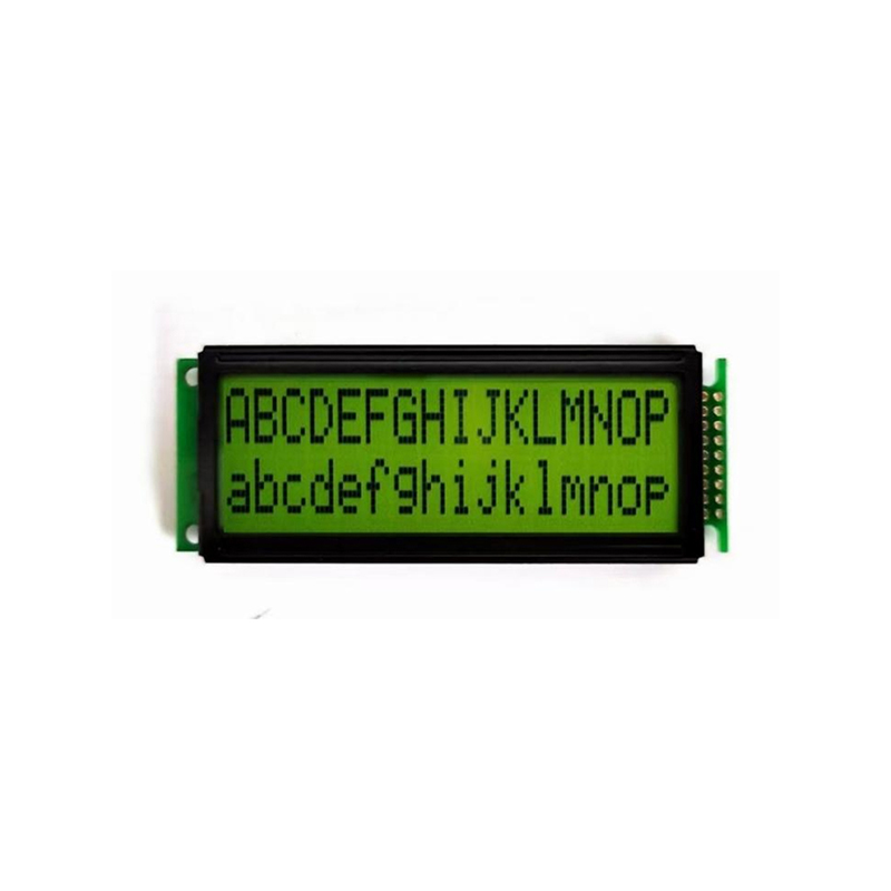
For a wide variety of high-quality LED displays and related components, consider exploring options from reputable suppliers. Remember to always check datasheets and specifications to ensure compatibility before purchasing. For example, you might find suitable options from Dalian Eastern Display Co., Ltd. They offer a diverse range of displays for various applications.
This guide provides a foundation for working with Arduino LED segment displays. Experiment with different libraries, explore advanced techniques, and unleash your creativity to build innovative and engaging projects.