Dalian Eastern Display Co., Ltd.
Dalian Eastern Display Co., Ltd.


This guide provides a detailed exploration of the Arduino Nano SPI interface, covering its functionalities, practical applications, and potential challenges. Learn how to effectively utilize the SPI protocol with your Arduino Nano for seamless communication with various devices and sensors. We'll delve into code examples, troubleshooting tips, and best practices to ensure a smooth development process.
SPI (Serial Peripheral Interface) is a synchronous, full-duplex communication protocol commonly used to connect microcontrollers like the Arduino Nano to peripherals such as sensors, displays, and memory chips. Its high speed and relatively simple implementation make it ideal for various applications. The Arduino Nano SPI interface provides four pins dedicated to SPI communication: MOSI (Master Out Slave In), MISO (Master In Slave Out), SCK (Serial Clock), and SS (Slave Select).
SPI operates by transmitting data bits synchronously using a clock signal. The master device (typically the Arduino Nano) controls the clock speed and initiates communication. Data is transferred bit by bit, with the master sending data on the MOSI pin and receiving data on the MISO pin. The SS pin is used to select individual slave devices. Understanding these basics is crucial for effective Arduino Nano SPI interface programming.
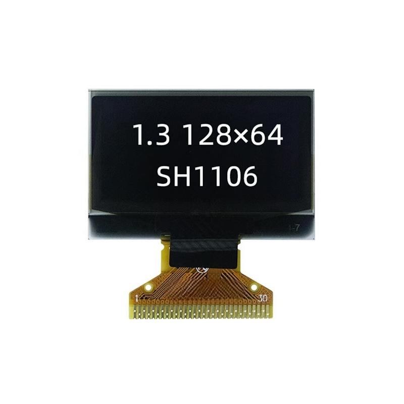
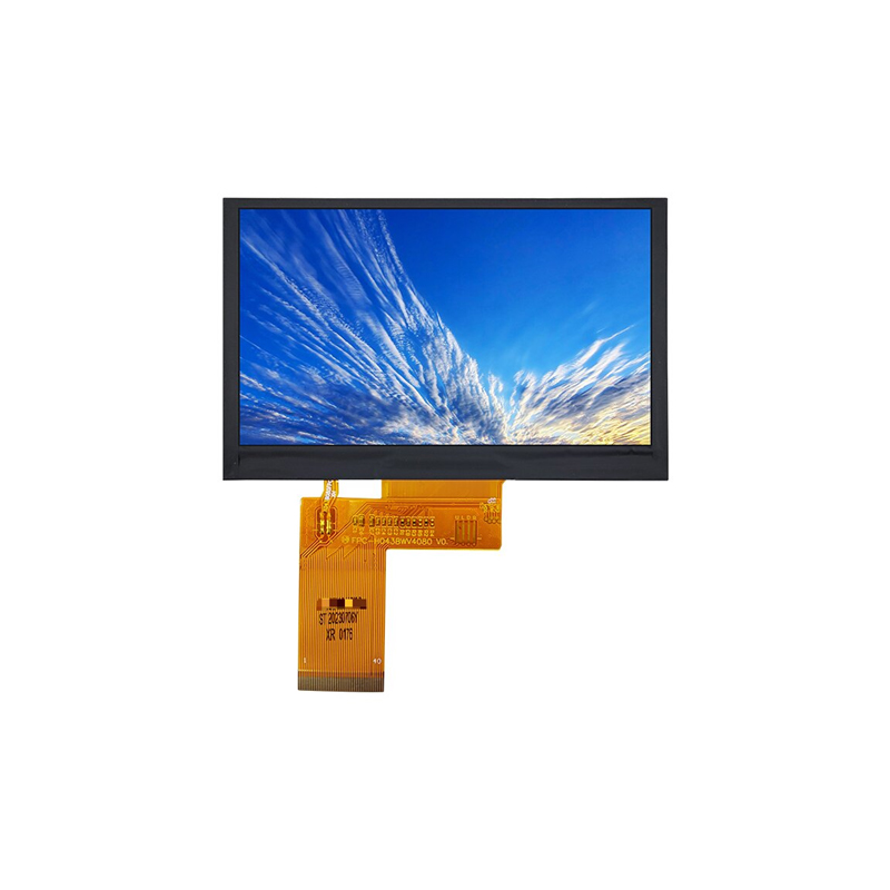
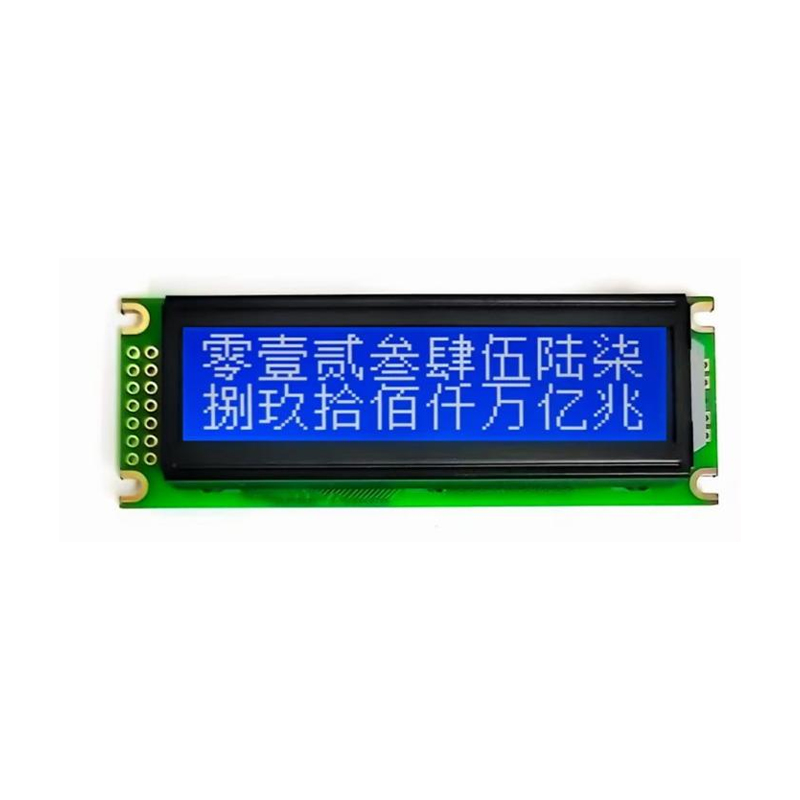
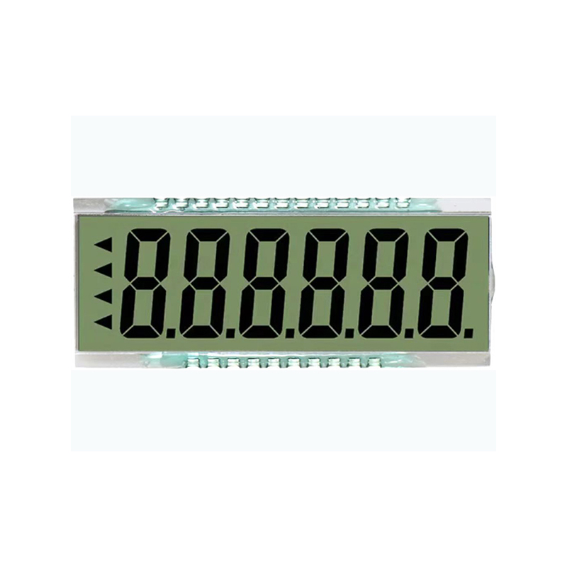
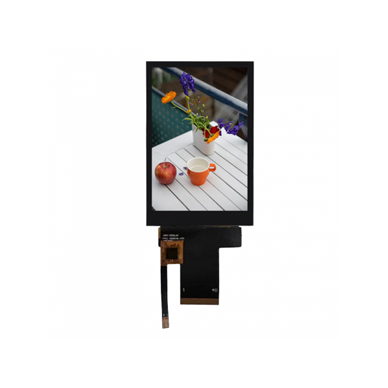
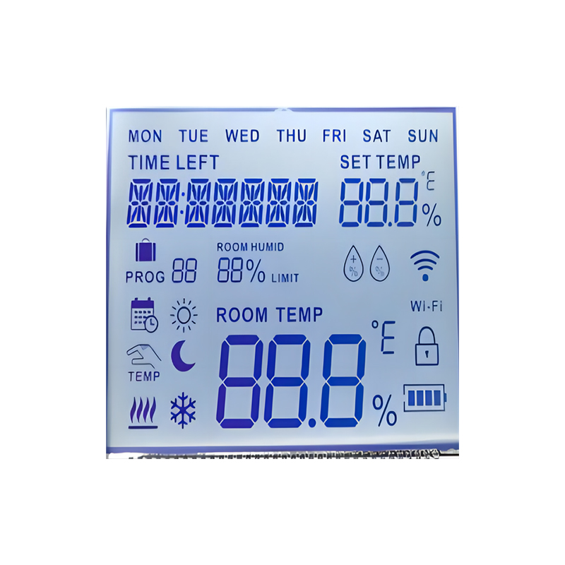
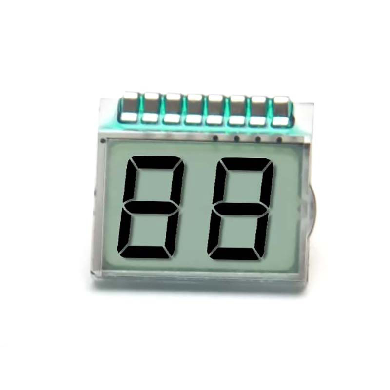
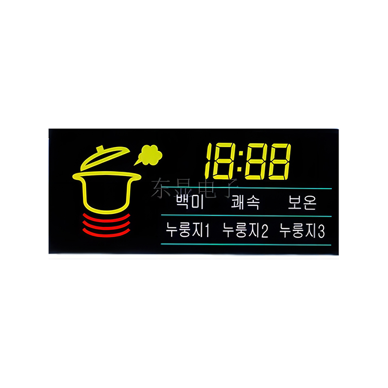
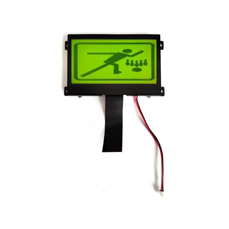
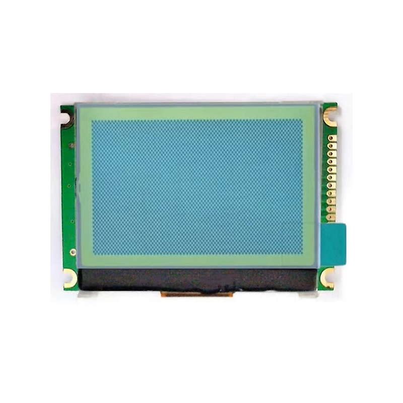
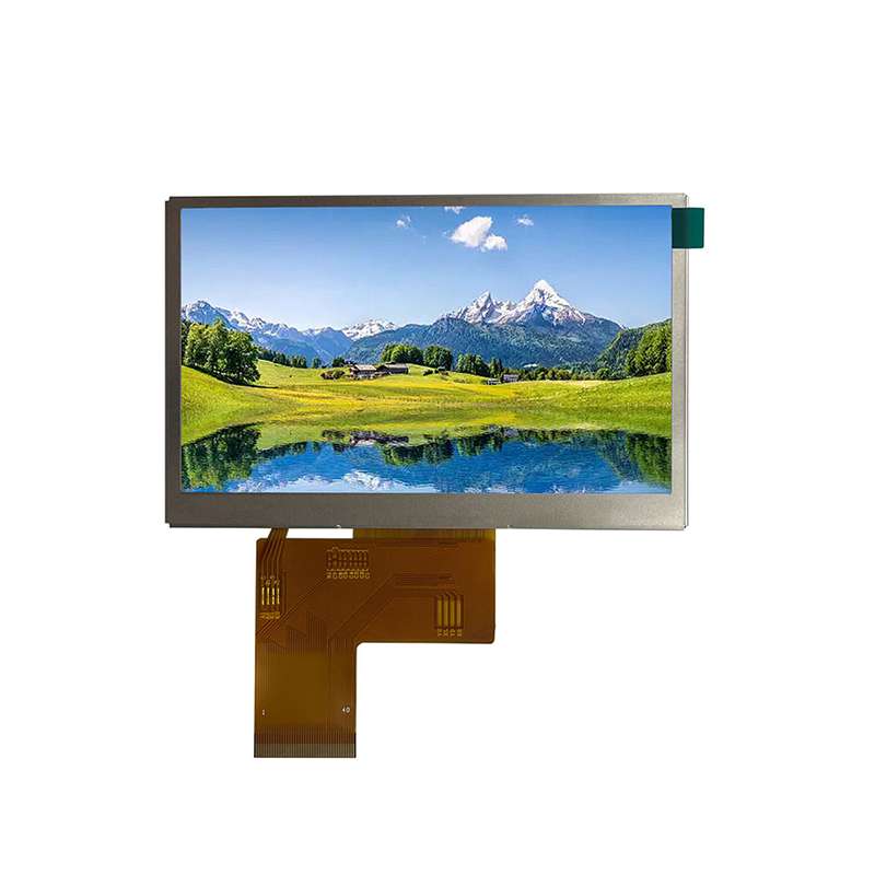
Many LCD displays utilize the SPI protocol for communication. Integrating an SPI LCD with your Arduino Nano SPI interface involves connecting the appropriate pins and using a suitable library. For example, the Adafruit_GFX and Adafruit_ILI9341 libraries provide support for various SPI LCDs. The specific connection details will vary based on your chosen LCD model; consult its datasheet for accurate pin assignments. A typical connection might involve: MOSI to MOSI, MISO to MISO, SCK to SCK, and a digital pin on the Arduino Nano to the LCD's CS (Chip Select) pin.
Several sensors, such as accelerometers, gyroscopes, and magnetometers, use SPI communication. Using the Arduino Nano SPI interface to connect these sensors provides high-speed data acquisition. You'll need to refer to the sensor's datasheet for pinouts and communication protocols. Libraries are often available to simplify the process of interfacing with these sensors, abstracting away the low-level SPI details.
Double-check your wiring carefully! Incorrect connections are a frequent source of problems when using the Arduino Nano SPI interface. Pay close attention to the MOSI, MISO, SCK, and SS pin assignments on both the Arduino Nano and the peripheral device.
Ensure that the clock speed used in your Arduino code matches the clock speed supported by the peripheral device. Using an incorrect clock speed can lead to communication errors. Consult your peripheral's datasheet to determine the appropriate clock rate.
If you're using libraries for SPI communication, make sure that they are properly installed and configured. Out-of-date or incompatible libraries can cause unexpected behavior.
The SPI bus' speed can be adjusted through the `SPI.beginTransaction()` function. Experimenting with different clock speeds might improve performance for specific applications, but remember to stay within the limits of your Arduino Nano and peripheral devices. Always consult the datasheets for maximum speeds.
The Arduino Nano SPI interface can communicate with multiple slave devices simultaneously by using separate SS pins to select each device individually. This technique enables efficient data acquisition from various sources.
| Peripheral | SPI Communication Speed (MHz) | Typical Applications |
|---|---|---|
| LCD Display (e.g., ILI9341) | Up to 10 MHz (varies by model) | Graphical User Interfaces |
| Accelerometer (e.g., MPU6050) | Up to 1 MHz (varies by model) | Motion Sensing, Orientation Tracking |
| SD Card | Up to 25 MHz (varies by card speed) | Data Storage |
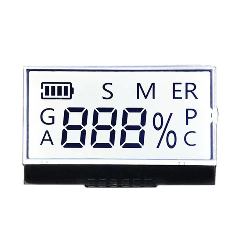
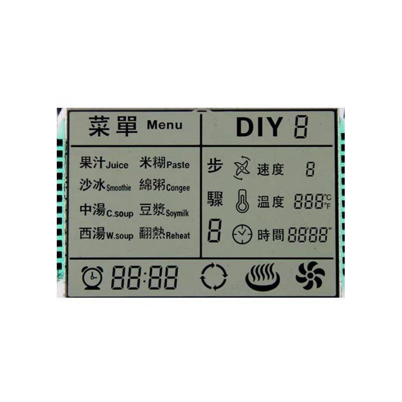
For more information on high-quality LCD displays, consider visiting Dalian Eastern Display Co., Ltd. They offer a wide range of display solutions. Remember to always consult the datasheets of your chosen components for specific technical details and limitations.