Dalian Eastern Display Co., Ltd.
Dalian Eastern Display Co., Ltd.


The SPI (Serial Peripheral Interface) bus is a synchronous, full-duplex communication protocol widely used in microcontrollers like the Arduino Nano. Understanding its capabilities is crucial for numerous projects involving sensors, displays, and other peripherals. This guide will walk you through everything you need to know about utilizing the Arduino Nano SPI interface effectively, from foundational concepts to advanced applications.
SPI operates using four main lines: MOSI (Master Out Slave In), MISO (Master In Slave Out), SCK (Serial Clock), and SS (Slave Select). The Arduino Nano acts as the master, controlling the communication speed and data flow. Each slave device connected via SPI has its own unique Slave Select (SS) pin, enabling the master to select and communicate with individual devices. This allows multiple devices to share the same SPI bus simultaneously.
The SPI clock speed (SCK) determines the communication rate. The Arduino Nano can support various speeds, adjustable via the SPI library. The bit order, whether it's Most Significant Bit (MSB) first or Least Significant Bit (LSB) first, is also configurable and depends on the specific slave device's requirements. Consult the datasheet of your chosen SPI device for the correct settings.
Connecting a device to the Arduino Nano SPI interface typically involves connecting the MOSI, MISO, SCK, and SS pins of the Arduino to the corresponding pins on the slave device. Remember to consult the device's datasheet for the pin assignments. Ensure proper voltage levels are maintained; if your device operates at a different voltage than the Arduino Nano (5V), you may need a level shifter.
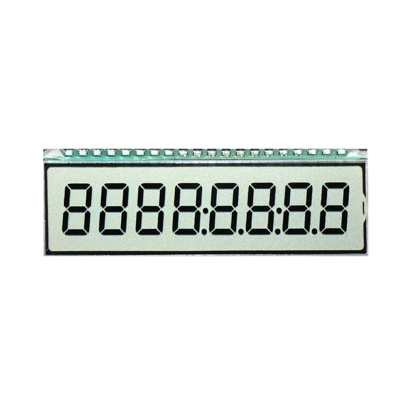
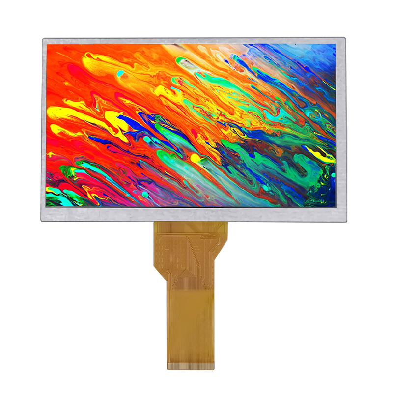
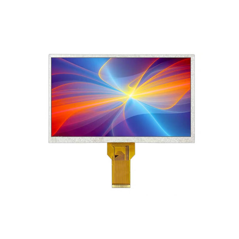
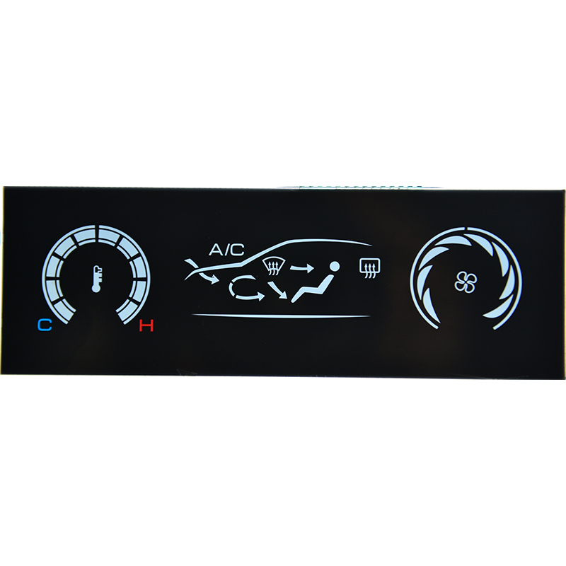
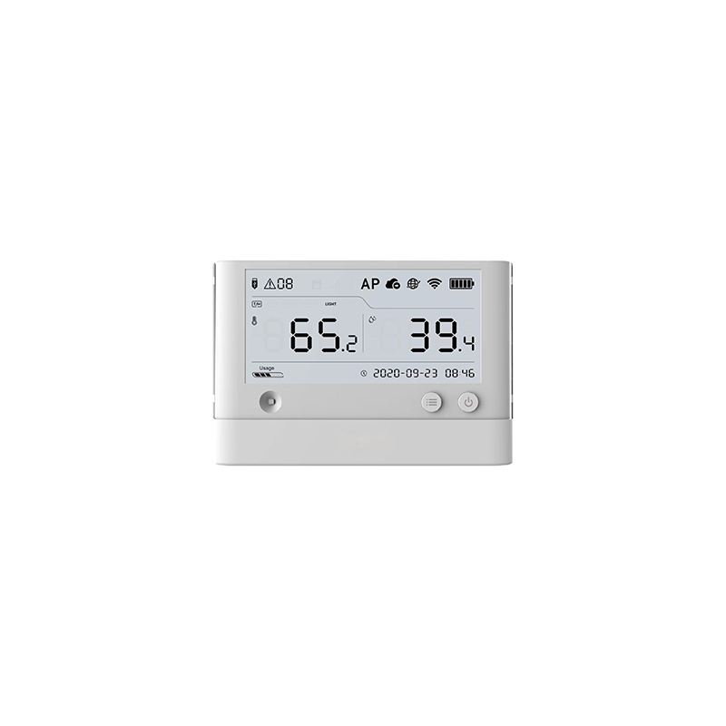
Many SPI displays, like those from Dalian Eastern Display Co., Ltd. (https://www.ed-lcd.com/), are readily available and easily integrated with the Arduino Nano. These displays often have detailed documentation on their pinouts and required SPI settings. For instance, a specific display might require a specific clock speed and bit order; these values must be configured accurately in the Arduino code.
The Arduino SPI library simplifies the process of communicating over the SPI bus. Functions like `SPI.begin()`, `SPI.transfer()`, and `SPI.beginTransaction()` offer convenient methods for data transmission and configuration. You'll need to specify the clock speed and data order appropriately.
#include <SPI.h>void setup() { Serial.begin(9600); SPI.begin(); SPI.beginTransaction(SPISettings(1000000, MSBFIRST, SPI_MODE0)); // Adjust speed and mode as needed}void loop() { byte data = SPI.transfer(0x01); // Send a byte and receive the response Serial.println(data, HEX); delay(1000);}If your Arduino Nano SPI interface isn't communicating, check the wiring, voltage levels, and SPI settings. Ensure the clock speed, bit order, and data mode are correctly configured according to the device's datasheet. Try printing debug messages to the serial monitor to identify potential issues.
Data corruption can result from improper wiring, clock speed issues, or timing problems. Start by checking the connections and ensuring the clock speed is not too high for your devices. Also verify the SPI mode is correctly set (SPI_MODE0, SPI_MODE1, etc.).
The Arduino Nano SPI interface supports a wide variety of devices. Here's a table showcasing a few examples:
| Device Type | Example | Application |
|---|---|---|
| SPI Display | ILI9341 | Graphical User Interfaces |
| Real-Time Clock (RTC) | DS3231 | Timekeeping |
| SD Card | Various SD card modules | Data Storage |
| Sensor | Many sensors with SPI interfaces | Data Acquisition |
Remember to always consult the device's datasheet for specific connection details and configuration instructions before integrating any new device with your Arduino Nano SPI interface product. The versatility of the SPI bus opens up countless possibilities for your embedded systems projects.