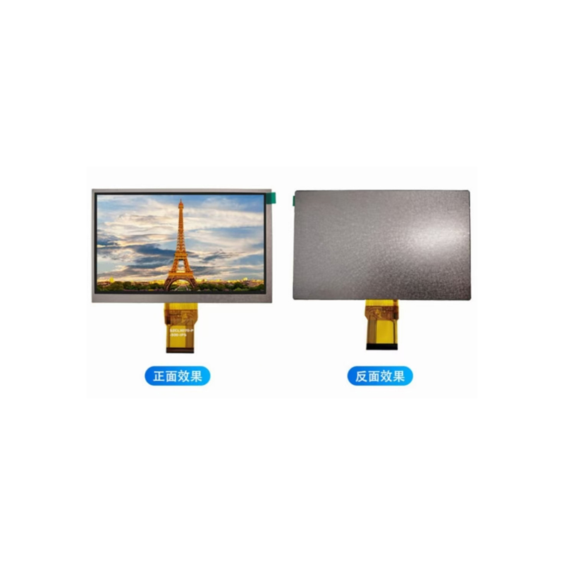
Arduino SPI Interface Factory: A Deep DiveThis guide provides a comprehensive overview of the Arduino SPI interface factory concept, covering its fundamentals, practical applications, and best practices for efficient implementation in various projects. We'll explore different aspects of SPI communication and highlight key considerations for successful integration.
Mastering the SPI interface is crucial for many Arduino projects. This guide delves into the intricacies of SPI communication, offering practical insights and actionable advice for developers working with Arduino-based systems. We'll examine common challenges and provide solutions for optimizing your Arduino SPI interface factory setup.
Understanding the Arduino SPI Interface
SPI Basics
SPI (Serial Peripheral Interface) is a synchronous, full-duplex communication bus used for short-distance communication, predominantly in embedded systems. It's a versatile protocol favored for its speed and simplicity, making it ideal for connecting various peripherals to an Arduino. Key characteristics include a master-slave architecture, where one device (the master, usually the Arduino) controls the communication, and multiple slaves can be connected.
SPI Pins on Arduino
Most Arduino boards have dedicated SPI pins: MOSI (Master Out Slave In), MISO (Master In Slave Out), SCK (Serial Clock), and SS (Slave Select). Understanding their functions is essential for proper configuration. The SS pin is used to select which slave device the master is communicating with.
Setting up SPI Communication
The Arduino IDE provides built-in functions for simplifying SPI communication. Using the `SPI.begin()` function to initialize the SPI bus is the first step. You'll need to specify the clock speed (using `SPI.setClockDivider()` for finer control), and the data order (MSBFirst or LSBFirst).
Practical Applications of Arduino SPI Interface Factory
Connecting Multiple SPI Devices
While an Arduino typically has only one SPI bus, managing multiple devices on a single bus is common practice. This involves careful handling of the Slave Select (SS) pins for each device to ensure only one device is addressed at a time. Poor management can lead to communication conflicts.
Example: Simultaneous Data Acquisition
Imagine a project requiring simultaneous data acquisition from multiple sensors using SPI. By carefully managing the SS pins and timing the communication, the Arduino can efficiently collect data from each sensor. This often involves writing custom code to handle the timing and data flow correctly.
Advanced SPI Techniques
Interrupt Handling
For high-speed or real-time applications, interrupt-driven SPI communication can significantly improve efficiency. By configuring interrupts on the SPI data pins, the Arduino can react instantly to data from peripherals, enhancing responsiveness.
DMA (Direct Memory Access)
On more advanced Arduino boards, DMA can further enhance SPI performance. DMA allows data transfer between peripherals and memory without CPU intervention, freeing up the Arduino for other tasks, leading to improved throughput and reduced latency. This is particularly beneficial in high-bandwidth applications.
Troubleshooting Common SPI Issues
Communication Errors
If your Arduino SPI interface factory setup isn't functioning correctly, communication errors may be the cause. Double-check your wiring, SPI settings (clock speed, data order), and ensure proper selection of the SS pins for each device.
Timing Issues
Synchronization errors are another common cause of problems. The clock speed and the timing between data bits must be carefully managed to avoid data corruption.
Software Glitches
Review your code carefully, ensuring no software-related issues affect data transfer. Consider using a logic analyzer for debugging the communication.
Conclusion
Effective utilization of the Arduino SPI interface factory requires a solid understanding of SPI communication, careful hardware design, and well-written software. By addressing the points raised in this guide, developers can successfully implement efficient and reliable SPI communication in their Arduino projects. Remember to consult the Arduino documentation and relevant datasheets for your specific hardware. For high-quality LCD displays to incorporate into your projects, consider exploring the options from
Dalian Eastern Display Co., Ltd. | SPI Setting | Description |
| Clock Speed | Determines the rate of data transfer. Higher speeds are faster but require more precise timing. |
| Data Order | Specifies whether the most significant bit (MSB) or least significant bit (LSB) is transmitted first. |
| Slave Select (SS) | Used to select individual devices on the SPI bus. |
This information is based on general knowledge of the Arduino SPI interface. Specific implementations might vary depending on the Arduino board and connected devices. Always refer to the official Arduino documentation for the most accurate and up-to-date information.


