Mastering the ESP8266 SPI Interface: A Comprehensive GuideThis guide provides a detailed walkthrough of effectively using the SPI interface with the ESP8266 microcontroller, covering setup, configuration, practical examples, and troubleshooting. We'll explore common use cases, potential pitfalls, and best practices for optimizing your Best ESP8266 SPI interface.
The ESP8266's versatility extends significantly through its SPI peripheral. This guide explores the intricacies of configuring and utilizing this crucial interface for various applications. We'll delve into code examples, hardware considerations, and troubleshooting techniques, ensuring a smooth integration into your projects. Whether you are a beginner or an experienced developer, this resource offers valuable insights into maximizing the ESP8266's capabilities via its SPI communication protocol.
SPI (Serial Peripheral Interface) is a synchronous, full-duplex communication bus that allows microcontrollers like the ESP8266 to communicate with peripheral devices. Its speed and efficiency make it ideal for tasks requiring high data throughput, such as interfacing with sensors, displays, and memory chips.
The ESP8266's SPI interface typically utilizes four signals:
Configuring the ESP8266 SPI interface involves setting parameters like clock speed, data order (MSB or LSB first), and data mode. These parameters are typically configured using the ESP8266's SDK (Software Development Kit).
Many projects leverage the ESP8266 to read and write data to an SD card via SPI. The specific code will vary depending on your SD card module and the chosen library (e.g., SD library for Arduino). Proper initialization and configuration of the SPI bus are crucial for successful data transfer. Here's a simplified conceptual example:
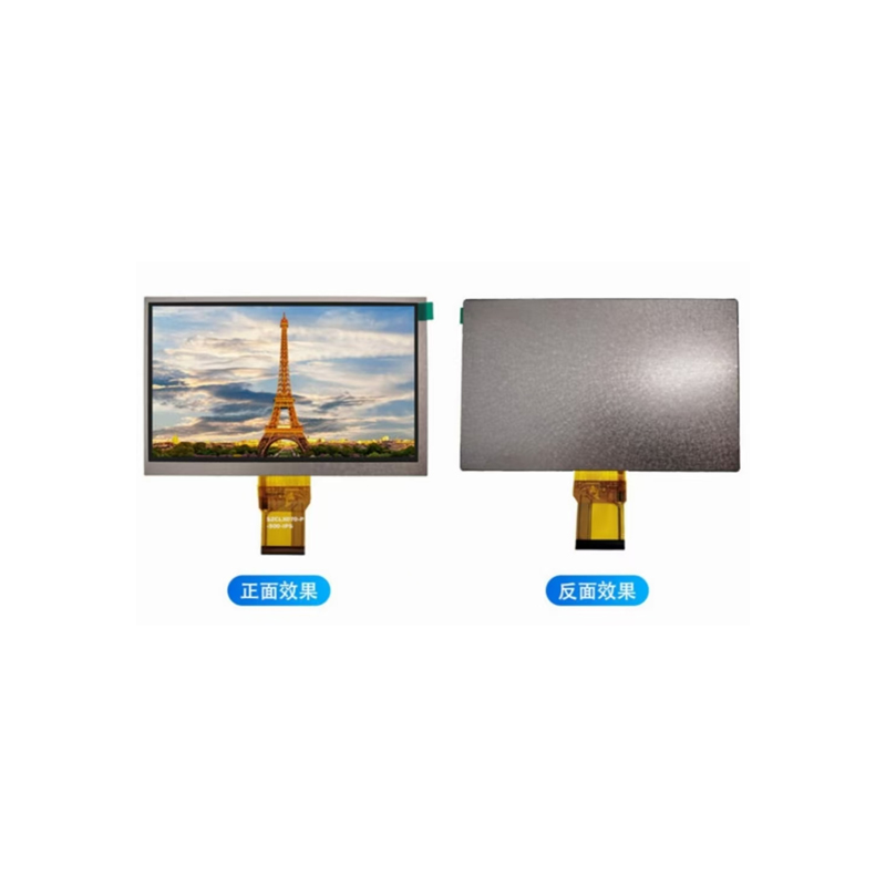
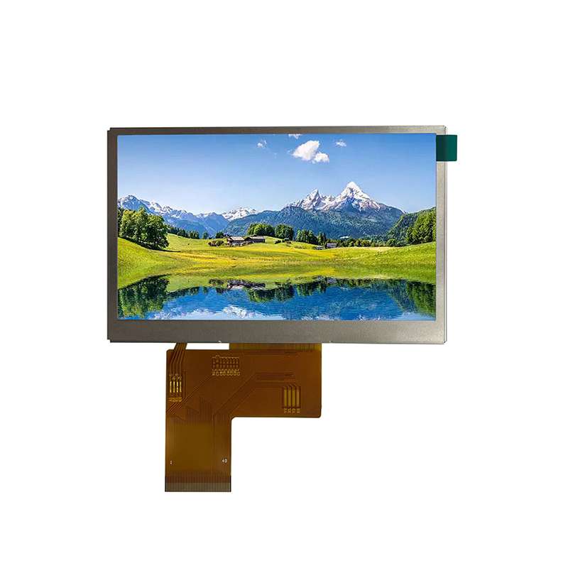
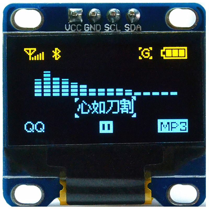
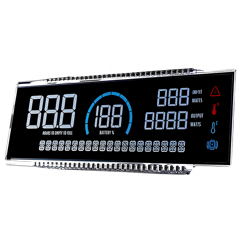
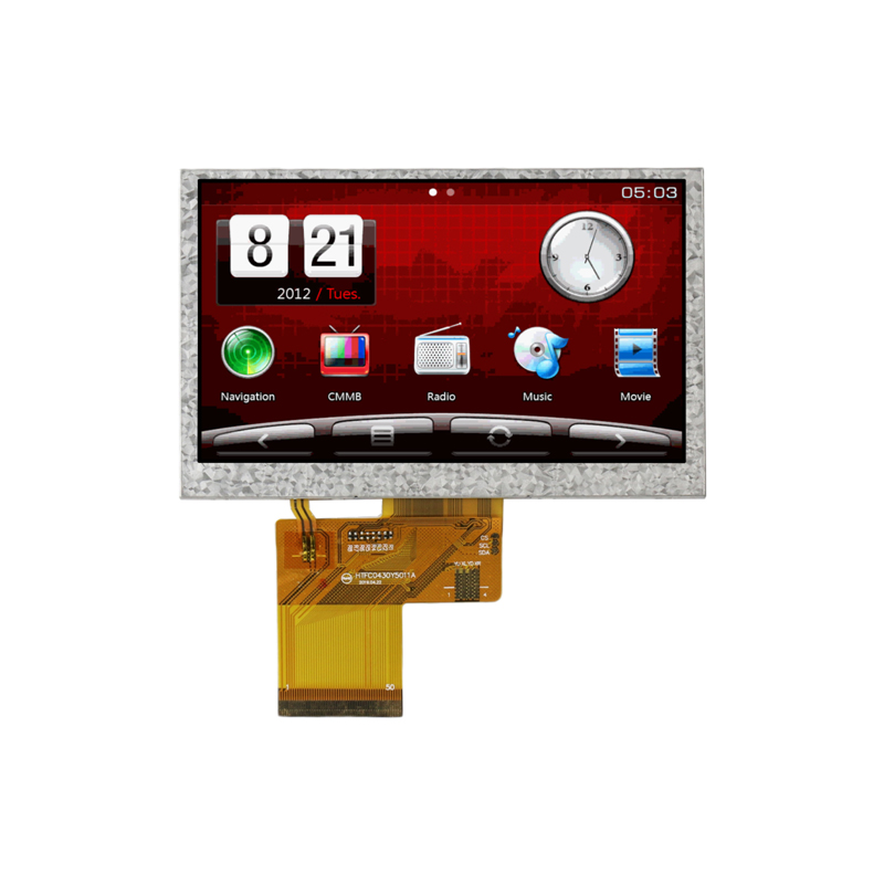
// Initialize SPISPI.begin();// Initialize SD cardif (!SD.begin(SS)) { Serial.println(Card failed, or not present); // ... error handling}// ... code to read/write data from/to SD cardConnecting and controlling an SPI display (e.g., ST7735, ILI9341) requires careful attention to the display's specifications, including the correct pin mapping and data format. The process involves initializing the display, setting up the SPI communication, and then sending commands and data to control its pixels.
If you're experiencing communication issues, double-check your wiring, SPI configuration settings, and the slave device's power supply. Ensure the clock speed is compatible with both the ESP8266 and the peripheral.
Data corruption can indicate problems with clock synchronization or incorrect SPI settings. Verify your data order (MSB/LSB) and data mode settings. Using a logic analyzer can aid in identifying timing issues.
For optimal performance, consider these factors:
Different ESP8266 modules offer varying capabilities. When selecting an ESP8266 SPI interface, consider factors like flash memory size, processing power, and the availability of necessary GPIO pins for SPI communication.
| Feature | ESP8266-01 | ESP8266-12 |
|---|---|---|
| Flash Memory | Limited | Larger capacity available |
| GPIO Pins | Fewer | More |
| Cost | Lower | Higher |
Remember to always consult the official datasheets and documentation for the specific ESP8266 module and peripheral devices you are using for accurate and reliable results. This comprehensive guide provides a strong foundation for successfully utilizing the ESP8266's SPI capabilities in your embedded systems projects. For high-quality LCD displays to complement your projects, consider exploring the range of products offered by Dalian Eastern Display Co., Ltd.


