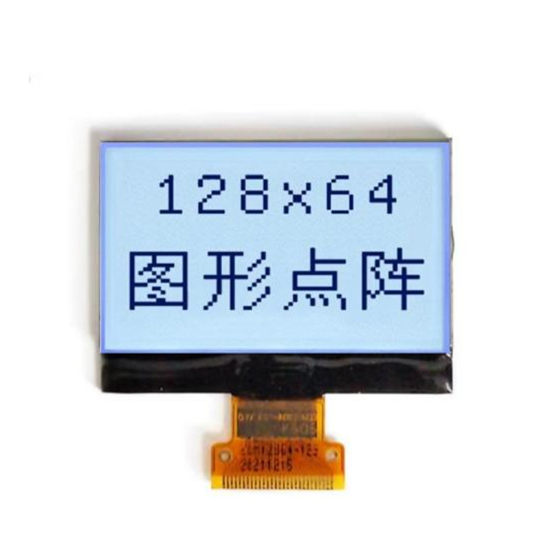
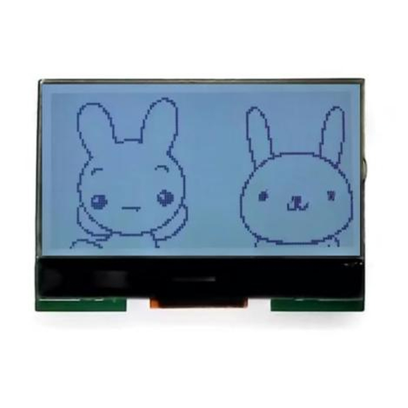
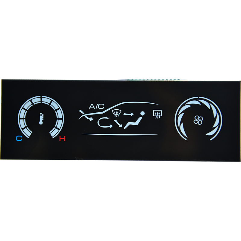
Dalian Eastern Display Co., Ltd.
Dalian Eastern Display Co., Ltd.


The Arduino Mega 2560 boasts a powerful SPI interface, a synchronous serial communication protocol ideal for high-speed data transfer. Understanding its factory defaults and how to configure them effectively is crucial for successfully integrating various peripherals such as displays, sensors, and memory chips. This guide provides a comprehensive walkthrough, equipping you with the knowledge to harness the full potential of the Mega 2560's SPI capabilities. We’ll delve into practical examples, troubleshooting common issues, and exploring advanced techniques to optimize your projects.
The SPI interface on the Arduino Mega 2560 operates in a master-slave configuration. The Mega 2560 typically acts as the master, controlling the communication and clock speed. Several pins are dedicated to SPI communication: MOSI (Master Out Slave In), MISO (Master In Slave Out), SCK (Serial Clock), and SS (Slave Select). These pins are usually hardwired to specific locations on the board, offering a dedicated and efficient communication path. The factory default settings for the SPI interface are generally sufficient for many applications, but understanding how to adjust them is critical for more demanding projects.
The Arduino Mega 2560's SPI interface, by default, operates at a frequency determined by the system clock. While the exact frequency depends on the Arduino Mega 2560 board variant and its configuration, it's typically high enough for many applications. The default mode often uses a clock polarity (CPOL) of 0 and a clock phase (CPHA) of 0, but this can be adjusted as needed using the SPI library functions. The Slave Select (SS) pin is usually pin 10, but this is also configurable. The precise factory settings might vary slightly depending on the specific manufacturer or board revision. Always refer to your board's documentation for the most accurate details.
While the factory defaults often work well, you might need to adjust the settings for optimal performance with certain devices. The Arduino SPI library simplifies this process. The primary parameters you can modify are:
SPI.setBitOrder(), SPI.setDataMode() and SPI.setClockDivider() functions to adjust these parameters based on your hardware specifications.digitalWrite() function to control these pins. Problems with the Best SPI interface Arduino Mega 2560 factory configuration can arise from incorrect settings, hardware problems, or compatibility issues. Troubleshooting often involves systematically checking the following:
For more complex applications, advanced techniques such as interrupt-driven SPI communication can significantly improve efficiency. Interrupts allow the Arduino to perform other tasks while waiting for SPI data transfers to complete, leading to better responsiveness. Utilizing libraries such as SPI and other advanced communication protocols might be necessary for increased efficiency. Always prioritize understanding the device specifications before implementing any advanced method.
Mastering the SPI interface on the Arduino Mega 2560 is essential for numerous projects. Understanding the factory settings and how to modify them efficiently unlocks a world of possibilities. By carefully following these guidelines and troubleshooting effectively, you can successfully integrate a wide range of SPI devices and develop robust and high-performance applications. Remember to always consult the official Arduino documentation and the datasheets of your specific hardware components for detailed specifications.
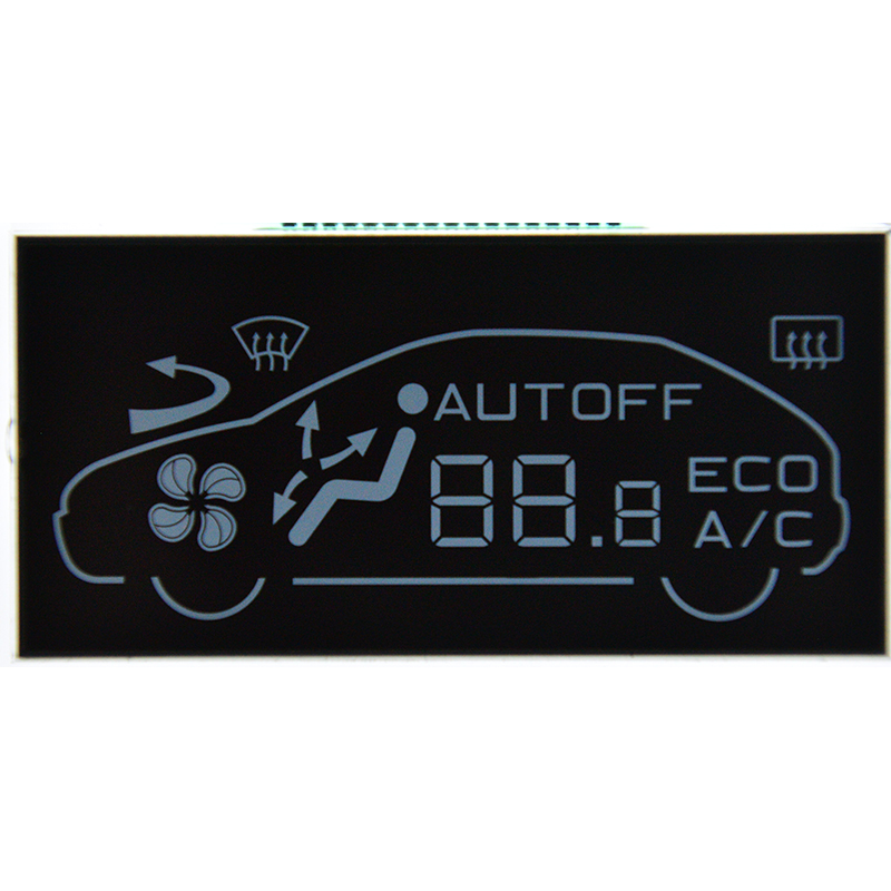
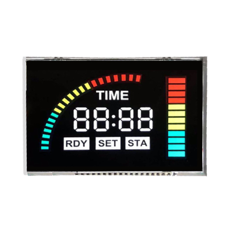
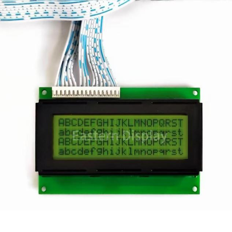
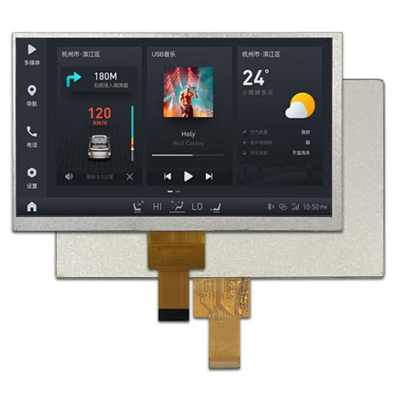
For more information about high-quality LCD displays, please visit Dalian Eastern Display Co., Ltd.