Dalian Eastern Display Co., Ltd.
Dalian Eastern Display Co., Ltd.


This guide provides a comprehensive overview of using the SPI interface with the ESP32 microcontroller, covering its functionalities, configuration, practical applications, and troubleshooting tips. Learn how to effectively integrate various SPI devices, optimize communication speed, and resolve common issues for seamless project implementation.
SPI (Serial Peripheral Interface) is a synchronous, full-duplex communication bus widely used to connect microcontrollers like the ESP32 to peripheral devices such as sensors, displays, and memory chips. Its speed and efficiency make it ideal for high-bandwidth applications. The ESP32 boasts multiple SPI peripherals, offering flexibility for diverse projects.
The ESP32 typically offers multiple SPI peripherals (SPI0, SPI1, and SPI2). Each peripheral uses several pins: MOSI (Master Out Slave In), MISO (Master In Slave Out), SCK (Serial Clock), and CS (Chip Select). The specific pins used can vary depending on the configuration and project requirements. Proper pin assignment is crucial for successful communication. Refer to your ESP32's datasheet for a complete pinout diagram.
The ESP32's SPI configuration involves setting up the SPI pins, clock speed, data order (MSB or LSB first), and data mode. This is typically done using the Arduino IDE or other development environments. Libraries like SPI simplify the process considerably. Correct configuration is essential for avoiding communication errors. Incorrect settings can lead to data corruption or no communication at all. A common issue involves incorrect selection of data mode.
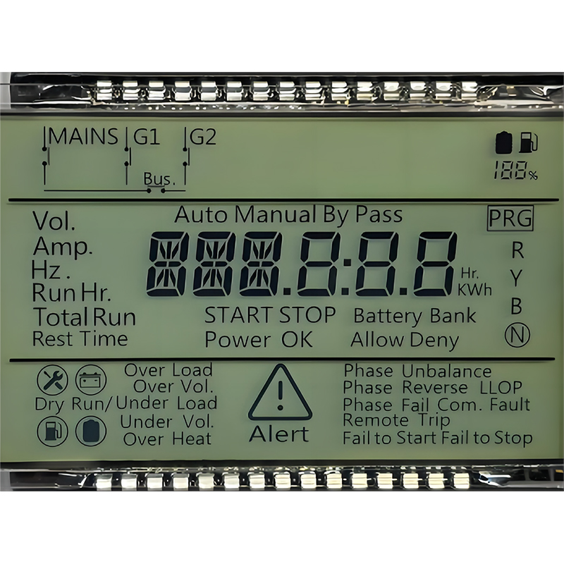
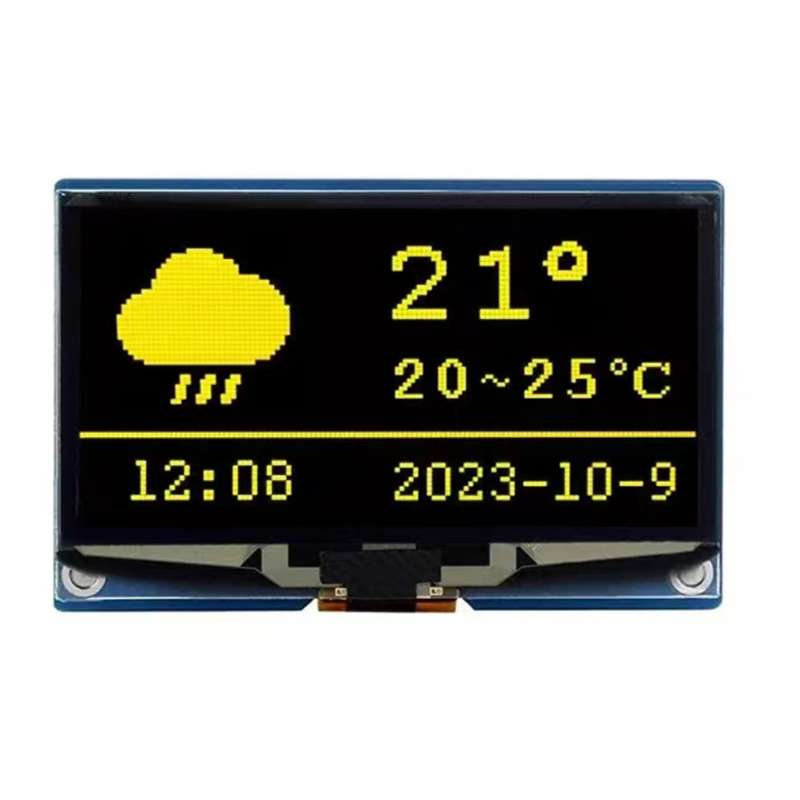
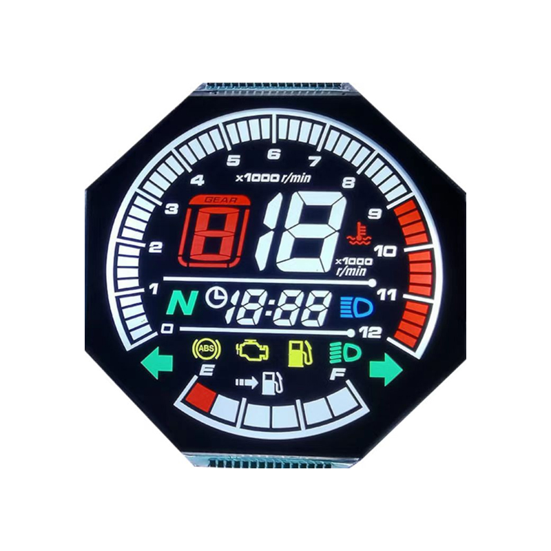
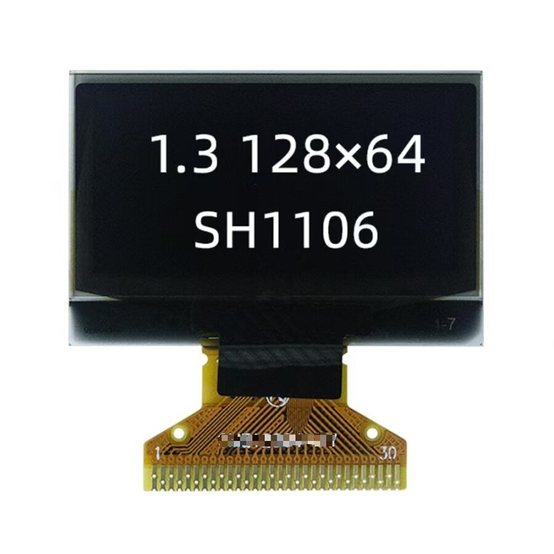
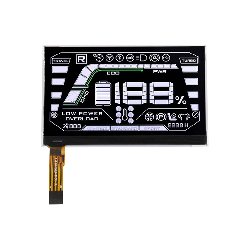
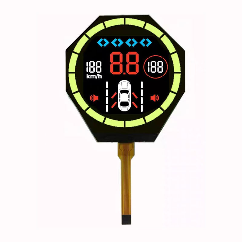
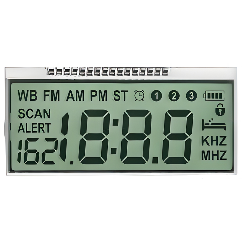
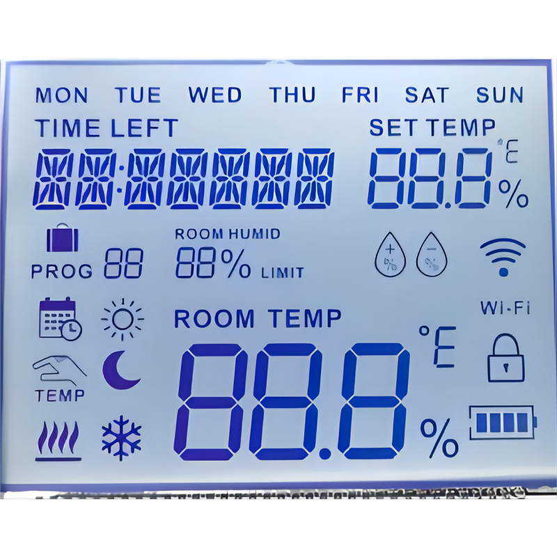
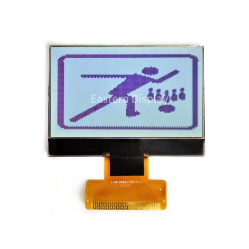
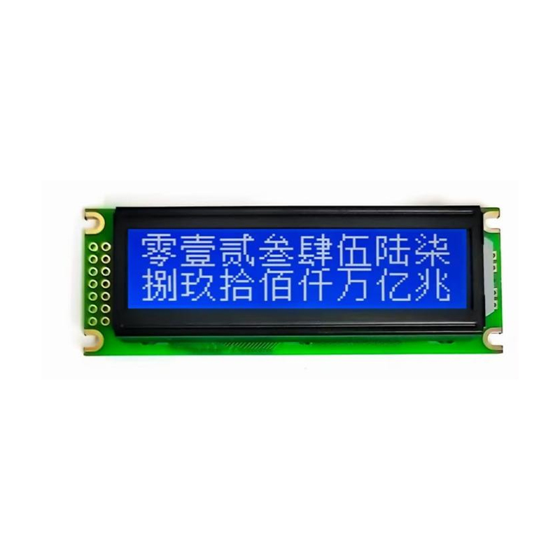
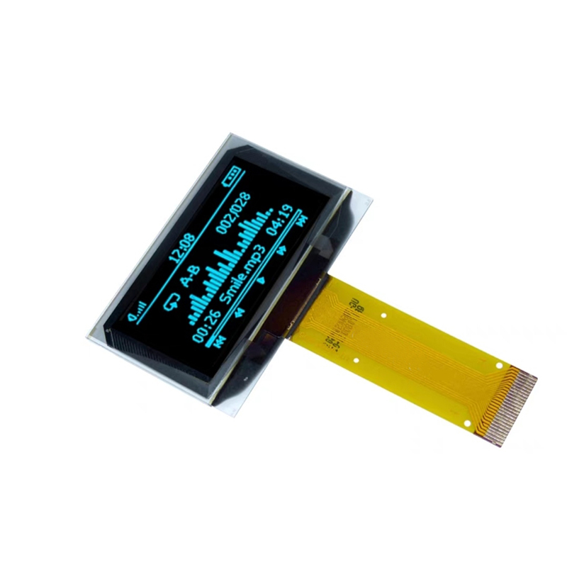
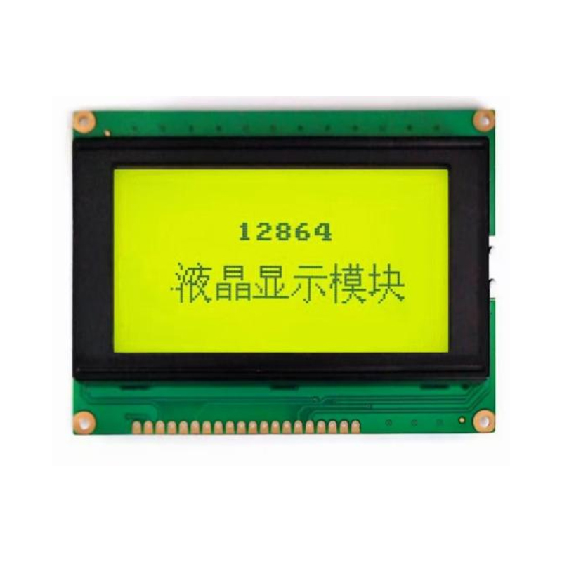
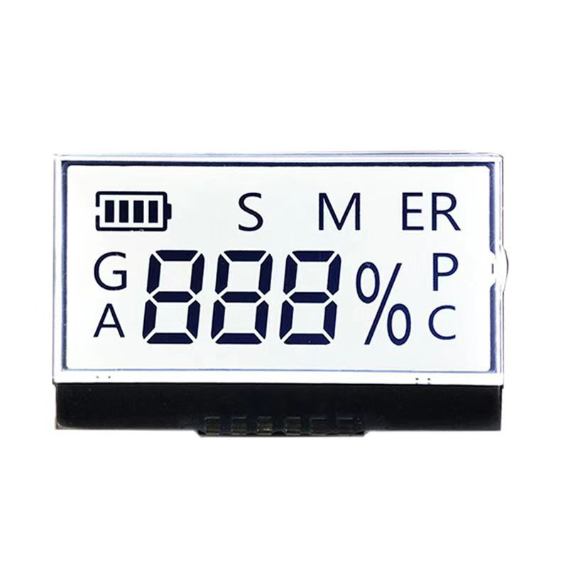
#include <SPI.h>// Define SPI pins#define SCK 18#define MISO 19#define MOSI 23#define CS 5void setup() { Serial.begin(115200); SPI.begin(SCK, MISO, MOSI, CS); // Initialize SPI SPI.setDataMode(SPI_MODE0); // Set data mode SPI.setBitOrder(MSBFIRST); // Set bit order SPI.setFrequency(1000000); // Set clock speed to 1MHz pinMode(CS, OUTPUT); // Set CS pin as output digitalWrite(CS, HIGH); // Set CS high initially}void loop() { // Your SPI communication code here}The ESP32's SPI interface is frequently used to drive various displays, including LCDs, OLEDs, and TFTs. Many display modules use SPI for communication. The specific setup will depend on the display's datasheet. Ensure to check the datasheet for pin connections, data format and communication speed.
Numerous sensors, such as accelerometers, gyroscopes, and magnetometers, employ SPI for data transmission. Using the Best SPI interface ESP32 offers high speed and low latency for real-time sensor data acquisition.
Troubleshooting SPI communication often involves verifying the wiring, SPI configuration, and the functionality of the connected device. Common problems include incorrect pin assignments, inappropriate clock speed, and faulty device connections. Using a logic analyzer can greatly help in identifying the root cause. Remember to consult your device's datasheet for detailed information and troubleshooting tips.
Selecting a compatible SPI device is crucial for successful integration. Compatibility depends on factors like voltage levels, clock speeds, and data protocols. Ensure that your chosen device is compatible with the ESP32's SPI capabilities. Always refer to the datasheets of both the ESP32 and the SPI device to ensure compatibility.
The ESP32's versatile SPI interface opens doors to a vast array of peripheral devices, making it a powerful choice for various embedded systems. Mastering its configuration and troubleshooting techniques is essential for successful project development. This guide provides a starting point for leveraging this valuable feature for your next project. Remember to always consult the relevant datasheets for detailed information.