Dalian Eastern Display Co., Ltd.
Dalian Eastern Display Co., Ltd.


This guide explores the intricacies of the Serial Peripheral Interface (SPI) bus and its effective implementation with microcontrollers. We'll delve into various aspects, comparing different approaches, providing practical examples, and addressing common challenges to help you select the best SPI interface with microcontroller for your project. Learn how to optimize your SPI communication for speed, reliability, and efficiency.
The Serial Peripheral Interface (SPI) is a synchronous, full-duplex communication bus commonly used to connect microcontrollers to various peripherals such as sensors, displays, memory chips, and more. Its simplicity and speed make it a popular choice for numerous embedded systems. A key advantage of SPI is its master-slave architecture, where one device acts as the master, controlling the communication, and other devices act as slaves, responding to the master's commands. Key characteristics include its four main lines: MOSI (Master Out Slave In), MISO (Master In Slave Out), SCLK (Serial Clock), and SS/CS (Slave Select/Chip Select).
SPI operates in different modes, defined by the clock polarity (CPOL) and clock phase (CPHA). These settings determine when data is sampled on the clock edge. Understanding these modes is crucial for proper communication. Incorrect mode selection can lead to data corruption. Refer to your microcontroller and peripheral datasheets for compatible modes. Common modes include Mode 0 (CPOL=0, CPHA=0), Mode 1 (CPOL=0, CPHA=1), Mode 2 (CPOL=1, CPHA=0), and Mode 3 (CPOL=1, CPHA=1).
Selecting the appropriate microcontroller depends on several factors, including the required processing power, memory capacity, peripheral interfaces, power consumption, and cost. Many microcontrollers, from low-power 8-bit devices to powerful 32-bit ARM-based MCUs, readily support the SPI protocol. Consider the number of SPI peripherals available on the microcontroller. Some MCUs offer multiple SPI interfaces, enabling simultaneous communication with multiple devices.
Several popular microcontroller families offer excellent SPI capabilities, including the STM32 (ARM Cortex-M series), ESP32 (ESP32-S series), and AVR (Atmel). Each family boasts various models with varying features and capabilities, allowing you to select the optimal solution based on your project's demands.
The SPI bus operates at a specific clock speed, determined by the SCLK signal. Increasing the clock speed increases the data transfer rate, but it can also compromise the stability of communication, especially with slower peripherals. Experiment to find the optimal balance between speed and reliability. Properly setting the SPI mode and ensuring correct timing are critical.
Implementing error handling mechanisms, such as parity checks or CRC (Cyclic Redundancy Check), can significantly improve the reliability of your SPI interface with microcontroller. These techniques detect data corruption during transmission and allow for appropriate error recovery.
Many microcontrollers offer dedicated hardware SPI peripherals, providing faster and more efficient communication. However, if hardware SPI is unavailable or insufficient, software SPI can be implemented, though it may be less efficient. Software SPI usually involves bit-banging, manually controlling the SPI pins. This approach should be avoided unless absolutely necessary.
The following code snippet illustrates basic SPI configuration and data transfer using the STM32 HAL library. Remember to adapt this code to your specific microcontroller and peripherals.
// ... STM32 HAL includes ...// SPI InitializationMX_SPI1_Init();// Data transmissionuint8_t data[] = Hello, SPI!;HAL_SPI_Transmit(&hspi1, data, sizeof(data), HAL_MAX_DELAY);Troubleshooting SPI communication issues often involves verifying the connections, confirming correct mode settings, and checking for clock speed compatibility. Ensure the Slave Select (SS) line is correctly managed to select the appropriate peripheral. Refer to datasheets for pin assignments and configurations. Using a logic analyzer can be incredibly helpful in debugging complex communication problems.
For further assistance and detailed information, consult your microcontroller's datasheet and the relevant peripheral datasheets. Effective utilization of the SPI interface with microcontroller hinges on understanding the intricacies of the protocol, careful component selection, and meticulous implementation.
| Microcontroller | SPI Features | Advantages | Disadvantages |
|---|---|---|---|
| STM32 | Multiple SPI interfaces, DMA support | High performance, flexible | Can be more complex to program |
| ESP32 | Multiple SPI interfaces, built-in Wi-Fi | Wireless capabilities, cost-effective | Higher power consumption compared to some alternatives |
| AVR | Simple SPI implementation | Easy to use, low cost | Lower performance compared to 32-bit MCUs |
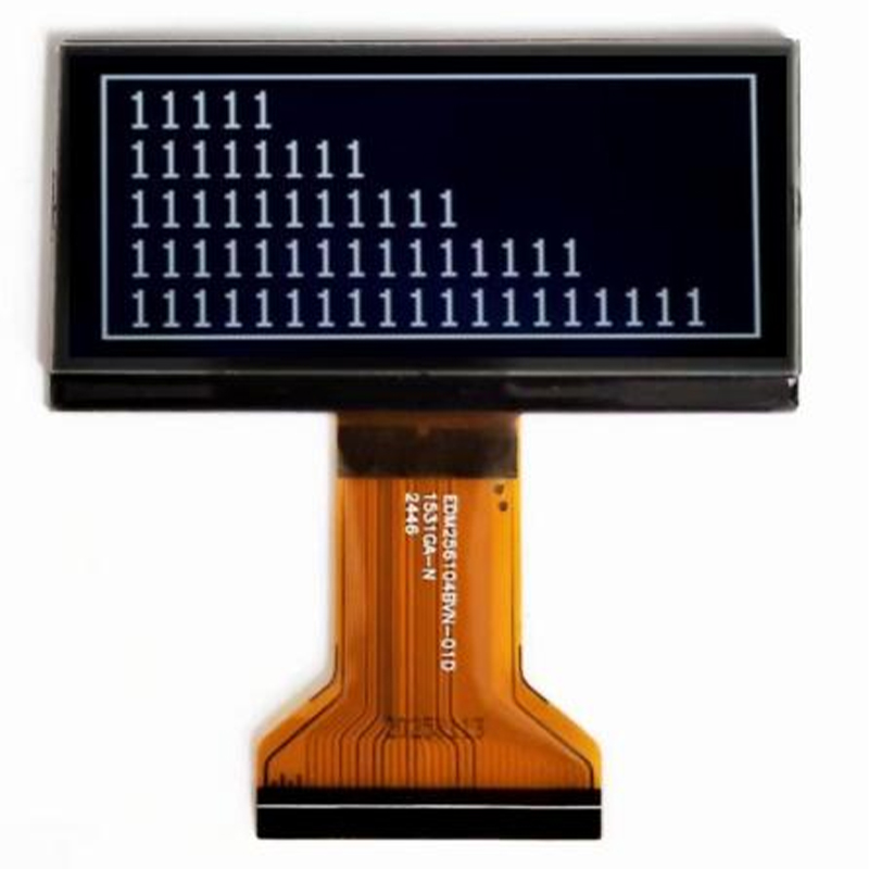
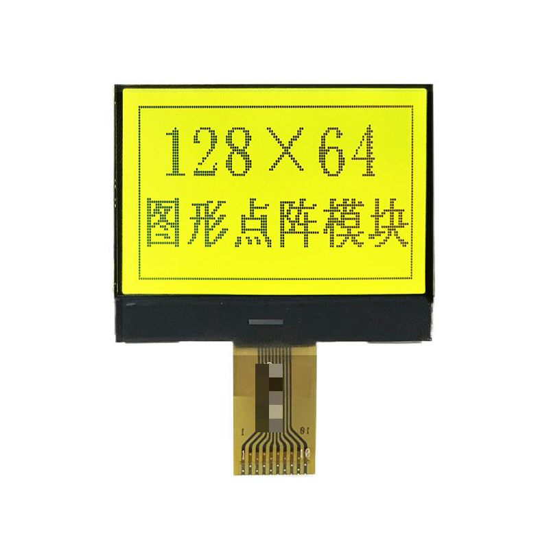
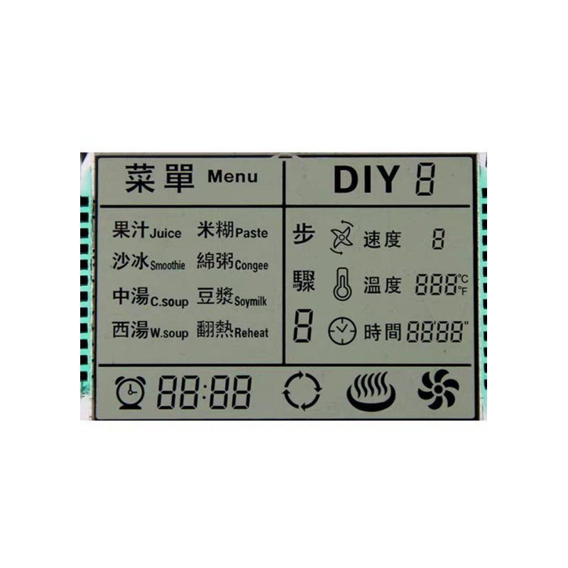
Looking for high-quality LCD displays for your embedded projects? Check out Dalian Eastern Display Co., Ltd. for a wide selection of options.