Dalian Eastern Display Co., Ltd.
Dalian Eastern Display Co., Ltd.


The Serial Peripheral Interface (SPI) bus is a widely used synchronous communication protocol for microcontrollers, enabling efficient data transfer between the microcontroller and peripherals like sensors, displays, and memory devices. Selecting the optimal Best spi interface with microcontroller product involves considering several crucial factors, including data rate requirements, device compatibility, and the microcontroller's capabilities. This guide will help you navigate these considerations and make informed decisions for your project.
Many microcontrollers support SPI communication. Popular families include ARM Cortex-M (found in many STM32, NXP LPC, and others), AVR (Atmel/Microchip), and ESP32. The specific SPI capabilities vary across families and even within a family. Key aspects to consider are the number of SPI ports, clock speeds, data bit order (MSB or LSB first), and the presence of advanced features such as DMA support for efficient data transfer. Always consult the microcontroller's datasheet for precise details on its SPI capabilities. For instance, the STM32 family offers a wide range of microcontrollers with varying numbers of SPI interfaces and clock speeds, allowing you to select the perfect fit for your application. Check out STMicroelectronics' STM32 range for more information.
The SPI clock speed is a critical factor influencing data transfer rate. Higher clock speeds result in faster communication, but they might not be supported by all peripherals. Always ensure the selected clock speed is compatible with both the microcontroller and the connected peripheral. Excessively high clock speeds can lead to communication errors. Properly configuring the SPI clock speed is essential for optimizing the Best spi interface with microcontroller product performance. Furthermore, the data sheet for the peripheral device should specify the maximum SPI clock speed it supports.
SPI operates in different modes, defined by the clock polarity (CPOL) and clock phase (CPHA). These parameters affect how data is sampled on the clock signal and must be configured consistently between the microcontroller and the peripheral. Incorrect configuration can result in communication failures. Refer to the SPI specification for a clear understanding of the different modes. Choosing the correct mode depends on the specific requirements of your target peripheral.
In a typical SPI configuration, one device acts as the master, initiating communication and controlling the clock speed, while the other device acts as the slave. The master sends the data to the slave or receives the data from the slave. Some applications might require multiple SPI devices acting as slaves to a single master. Understanding these roles is essential for properly configuring your system.
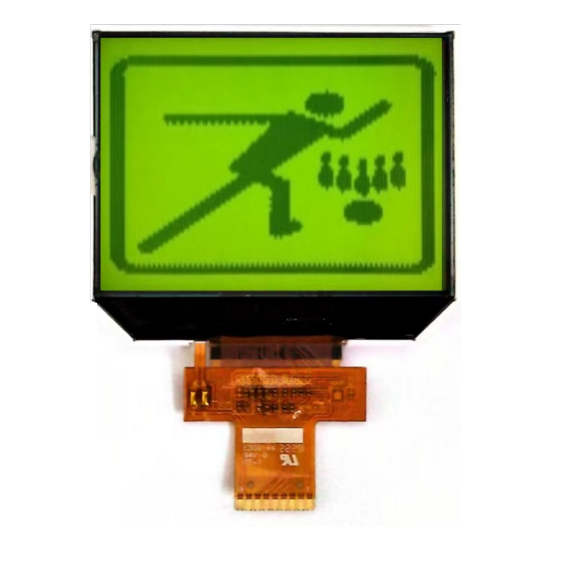
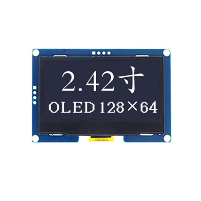
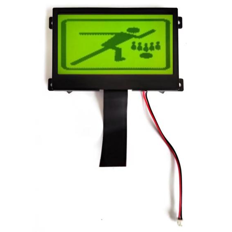
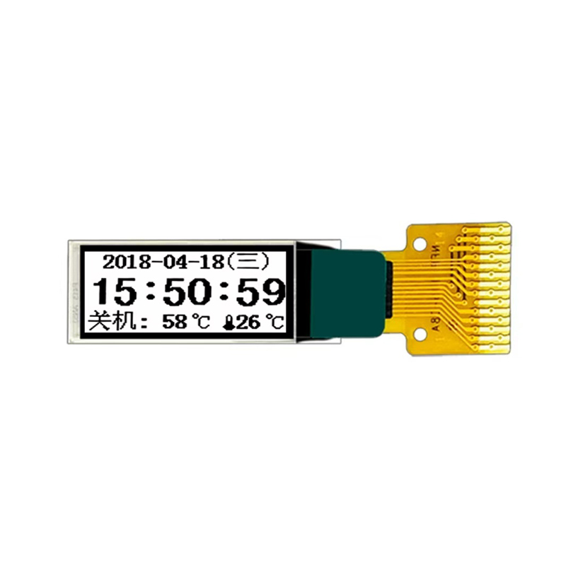
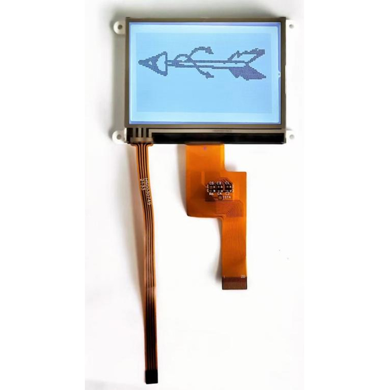
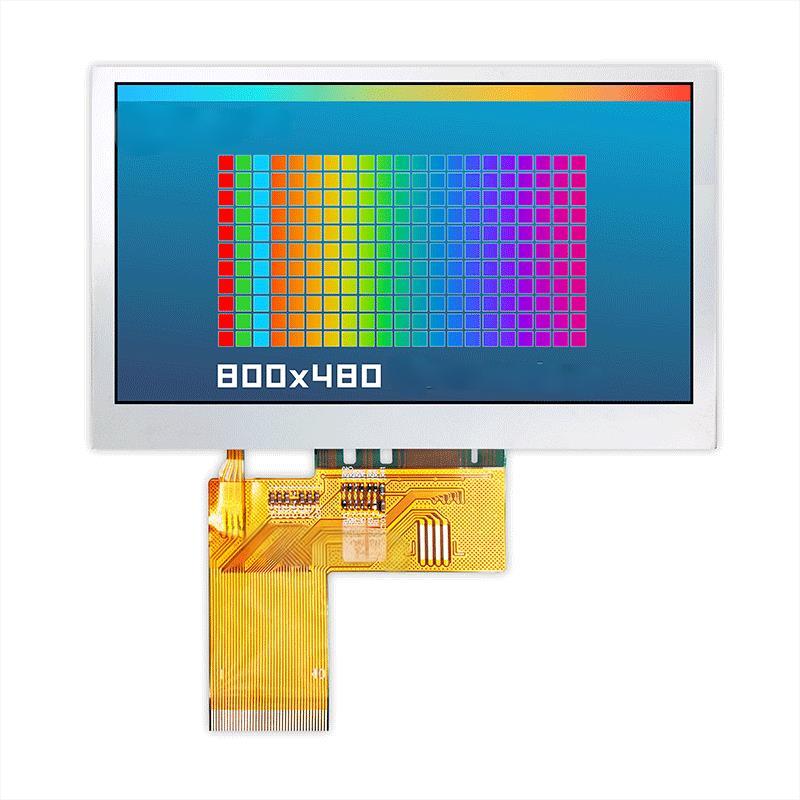
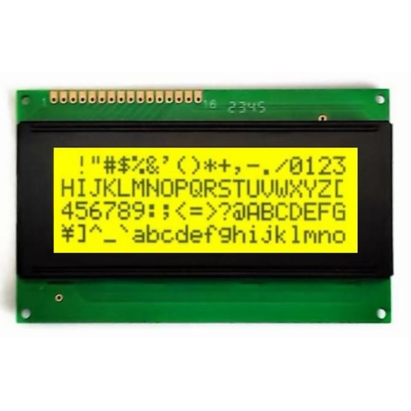
Many LCD and OLED displays use SPI communication. The process usually involves initializing the display, configuring the SPI settings (clock speed, mode, etc.), and then sending commands and data to control the display. The exact procedure depends on the specific display model and its datasheet. Several libraries and examples are available online for simplifying this process. Examples can be found in the documentation of various display manufacturers.
Numerous sensors utilize SPI for data acquisition. Similarly to display integration, the process involves configuring the SPI settings on the microcontroller and interpreting the data received from the sensor. Understanding the sensor's communication protocol and data format is crucial. Many sensor manufacturers offer detailed application notes and example code to aid in integration.
Direct Memory Access (DMA) controllers can significantly improve SPI efficiency by offloading data transfers from the CPU. This allows the microcontroller to perform other tasks while the SPI communication is handled by the DMA. The specific implementation varies depending on the microcontroller's architecture. Utilizing DMA can reduce the CPU load and enhance overall system performance, especially when dealing with large data transfers.
SPI communication can be susceptible to errors due to clock mismatches, noise, or incorrect configuration. Implementing appropriate error-handling mechanisms is crucial. Checking for errors, implementing retries and data verification steps are essential for robust SPI communication. For example, using CRC (Cyclic Redundancy Check) to verify data integrity adds a layer of protection.
| Feature | Microcontroller A | Microcontroller B |
|---|---|---|
| SPI Ports | 2 | 4 |
| Max SPI Clock Speed | 50 MHz | 100 MHz |
| DMA Support | Yes | Yes |
This comparison highlights the key differences between two hypothetical microcontrollers, demonstrating how these factors influence the choice of a Best spi interface with microcontroller product. Always consult the manufacturer's datasheets for accurate specifications.
By carefully considering the factors outlined in this guide, you can effectively select and implement the Best spi interface with microcontroller product for your specific application, ensuring efficient and reliable communication between your microcontroller and peripherals. Remember to consult the datasheets of your chosen microcontroller and peripherals for detailed specifications and application notes.