Dalian Eastern Display Co., Ltd.
Dalian Eastern Display Co., Ltd.


This guide provides a detailed explanation of the CPLD SPI interface, covering its fundamentals, practical applications, and potential challenges. Learn how to effectively configure and utilize SPI communication with CPLDs for various embedded systems designs. We'll explore different aspects, from basic concepts to advanced techniques, ensuring you have a solid understanding of this crucial interface.
Serial Peripheral Interface (SPI) is a synchronous, full-duplex communication bus used for short-distance communication, primarily in embedded systems. It’s characterized by its simplicity and speed, making it a popular choice for connecting microcontrollers, sensors, and other peripherals. A key advantage is its relatively low pin count compared to other interfaces.
The CPLD SPI interface typically uses four signal lines:
Proper hardware configuration is critical for a successful CPLD SPI interface. This involves selecting appropriate CPLD pins for each signal, ensuring correct voltage levels, and considering signal integrity. The choice of CPLD will depend on the complexity of your application and required performance.
The software configuration involves programming the CPLD to respond correctly to SPI commands. This often includes configuring specific registers within the CPLD to handle data transfer and control signals. The specifics will vary depending on the CPLD's architecture and the chosen programming language (e.g., VHDL, Verilog).
Let's consider a scenario where you're using a Xilinx CPLD. The process would involve:
Detailed examples and code snippets can be found in the Xilinx documentation and various online resources. Remember to consult the datasheets for your specific CPLD for accurate pin assignments and register configurations.
Different SPI modes (modes 0-3) define the clock polarity and phase, influencing the timing of data transfer. Understanding these modes is essential for establishing correct communication. Your microcontroller and CPLD must be configured to use the same SPI mode.
Implementing robust error handling is crucial in any communication system. This could include parity checks, checksums, or other error detection and correction mechanisms. Ensuring data integrity is paramount, especially in critical applications.
For high-speed applications, optimizing the clock frequency and carefully considering signal integrity (e.g., minimizing trace lengths and using appropriate termination) is vital. High-speed SPI may necessitate advanced techniques like differential signaling.
Troubleshooting a malfunctioning CPLD SPI interface often involves systematic checking of hardware connections, software configuration, and signal integrity. Utilizing logic analyzers or oscilloscopes can be invaluable for identifying timing issues or data corruption.
Remember to always consult the datasheets of your specific CPLD and microcontroller for detailed information and specific instructions. This comprehensive guide provides a strong foundation for understanding and mastering the CPLD SPI interface, empowering you to design robust and efficient embedded systems.
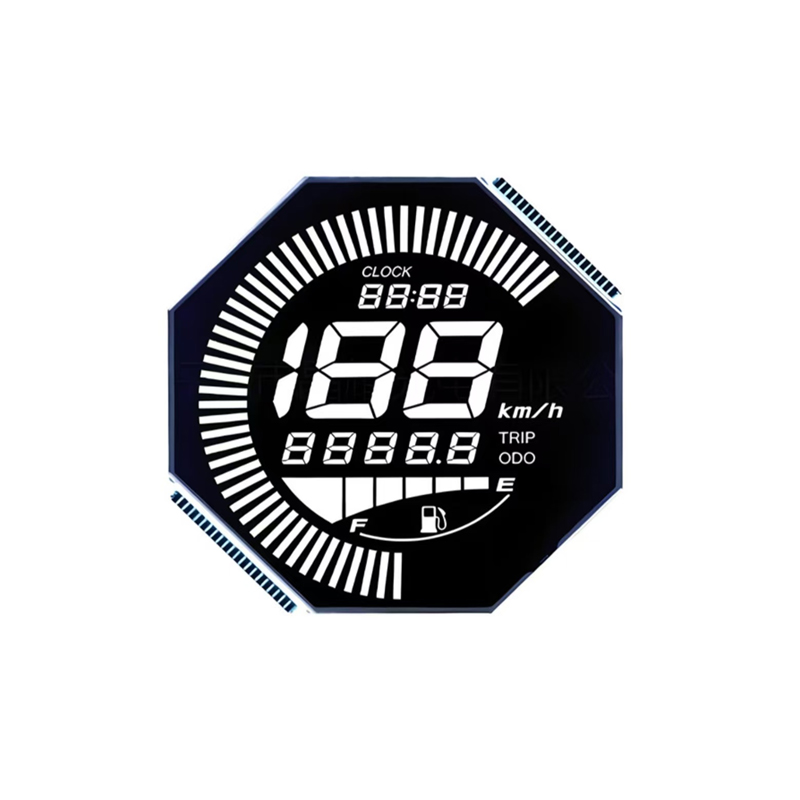
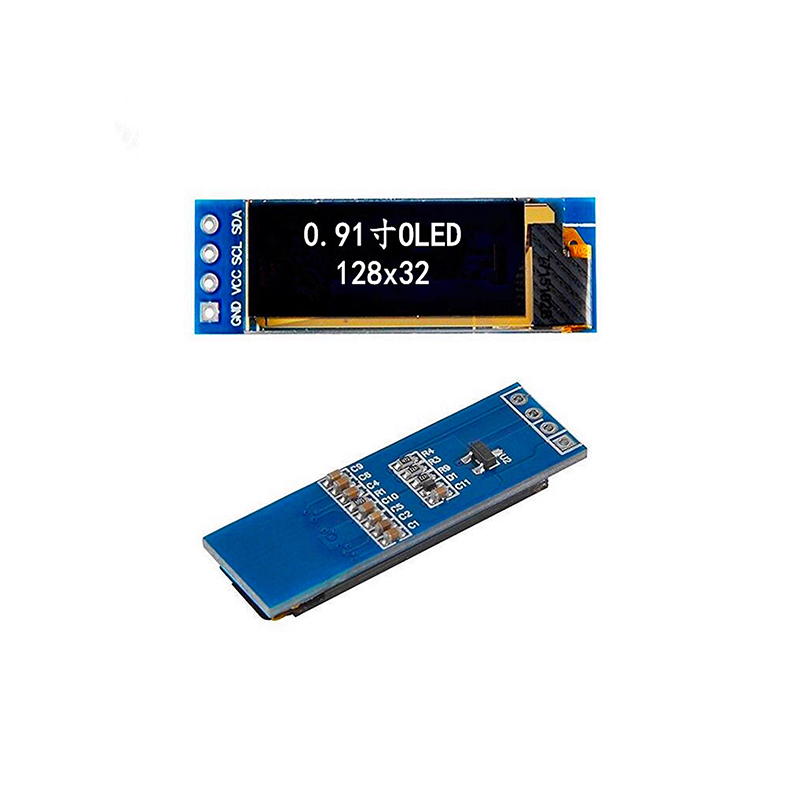
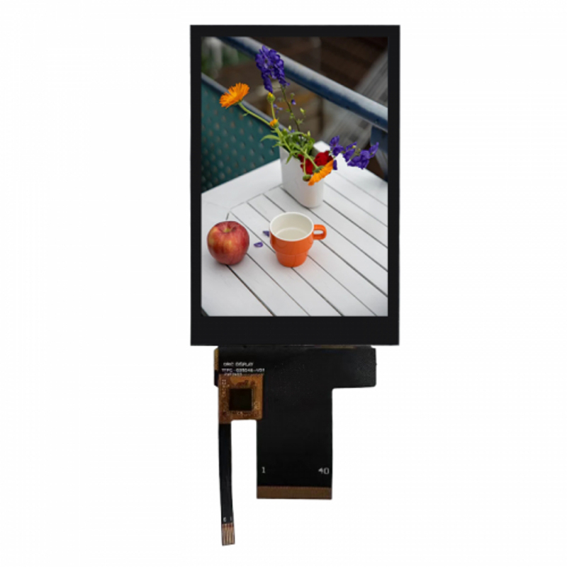
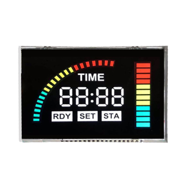
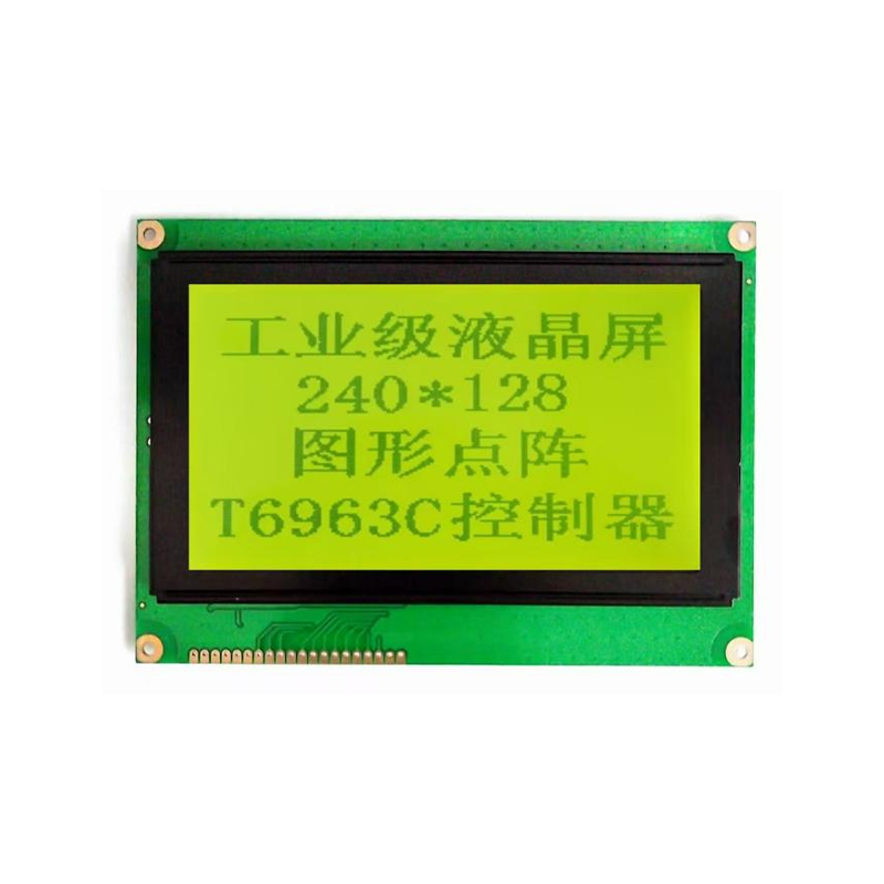
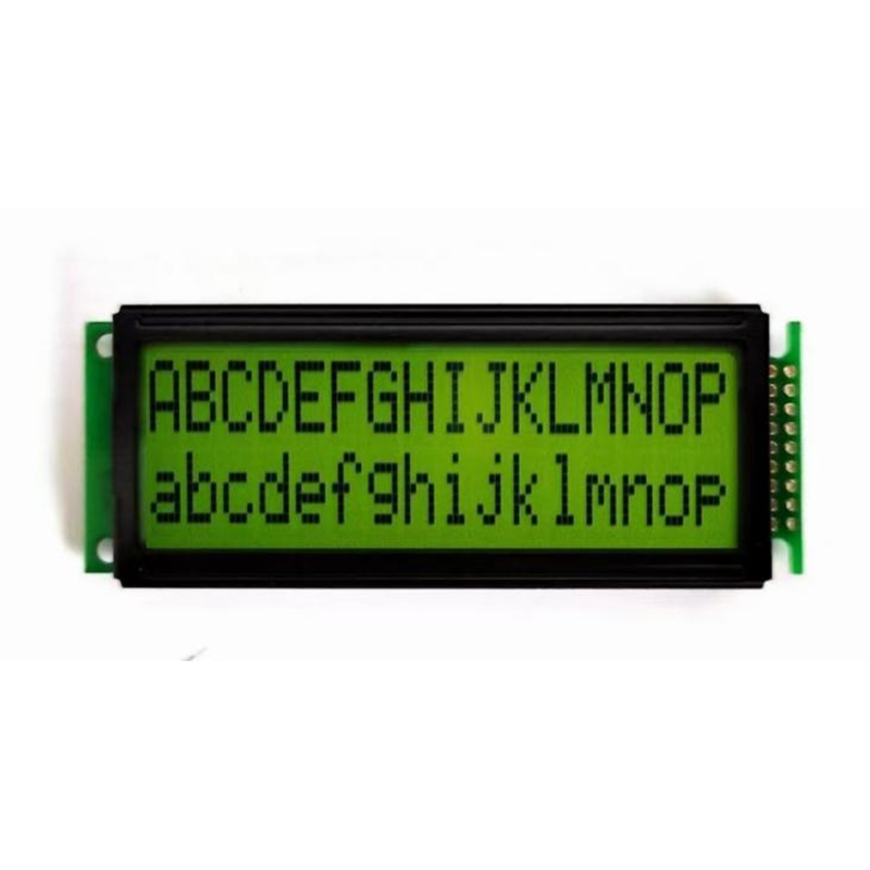
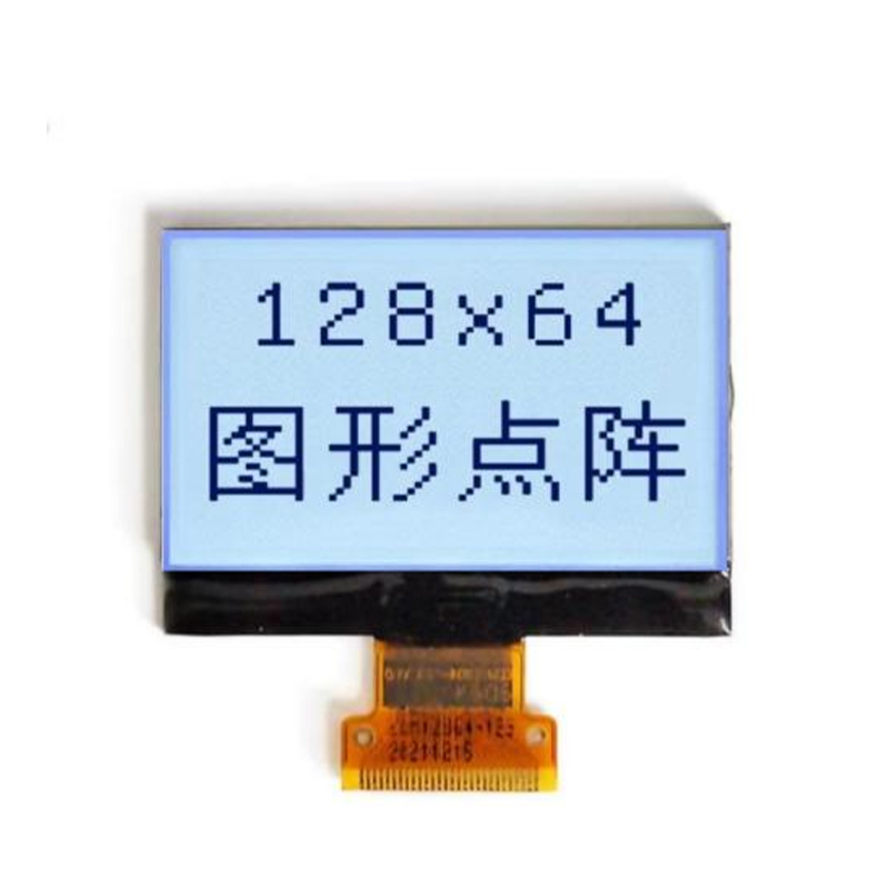
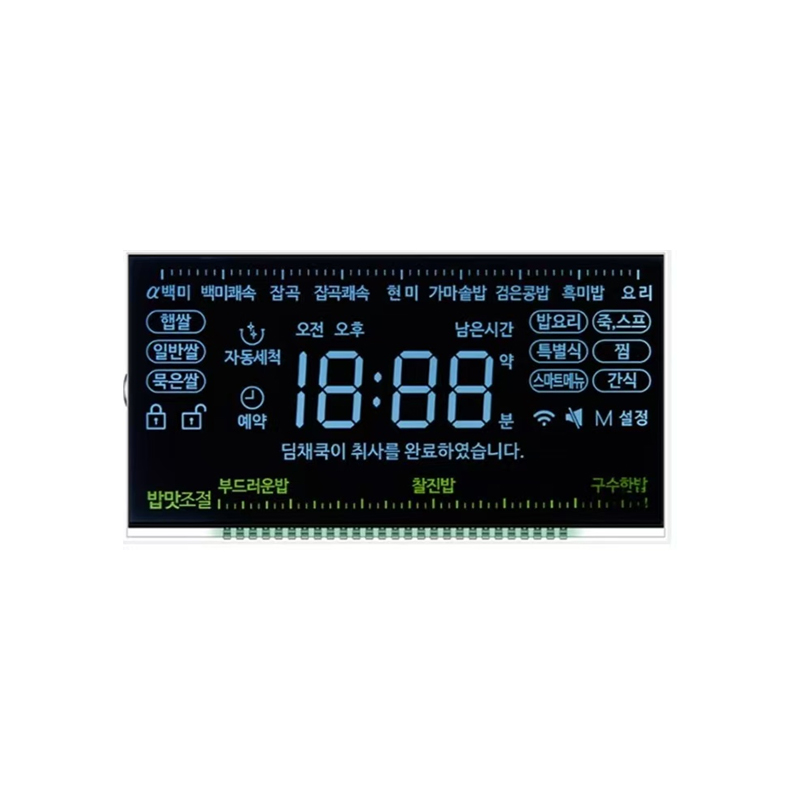
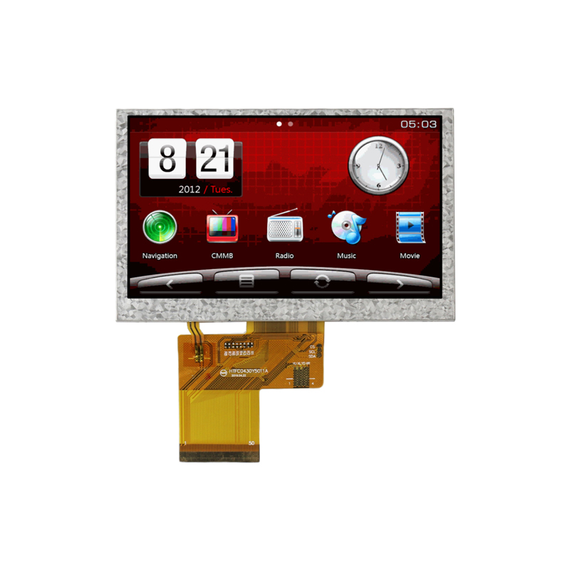
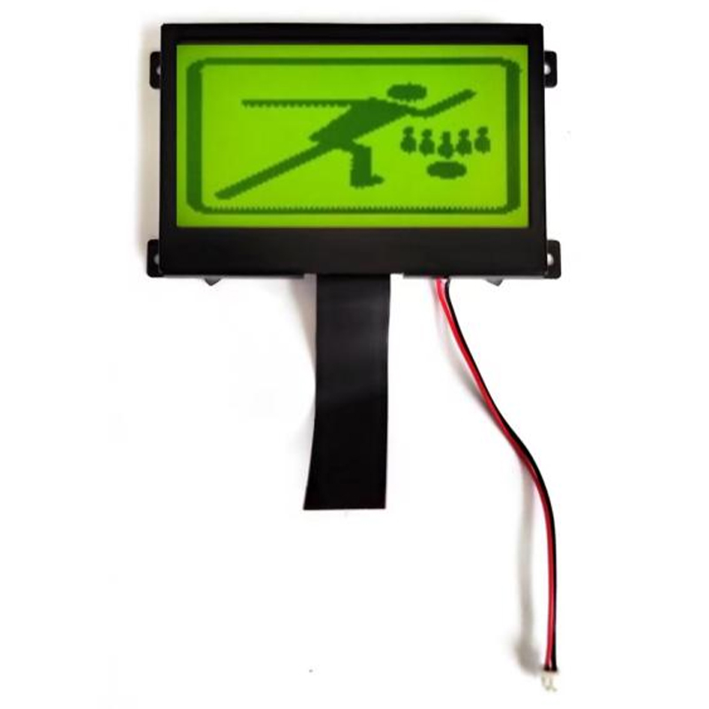
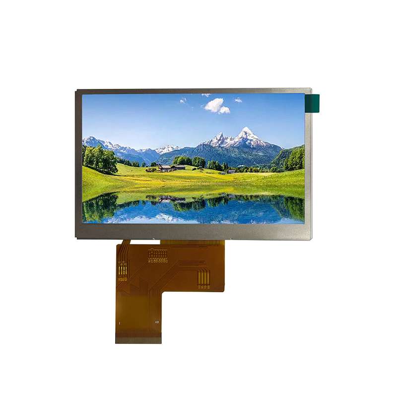
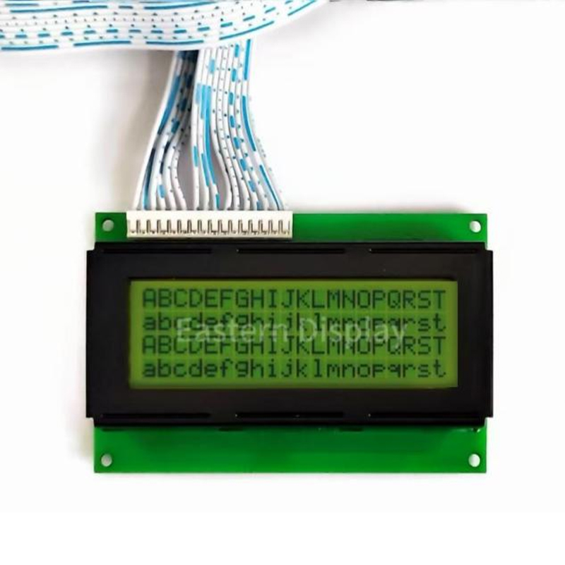
For high-quality LCD displays to integrate into your CPLD projects, consider exploring the options at Dalian Eastern Display Co., Ltd. They offer a wide range of displays suitable for various applications.