Dalian Eastern Display Co., Ltd.
Dalian Eastern Display Co., Ltd.


The Serial Peripheral Interface (SPI) is a synchronous, full-duplex communication bus commonly used for short-distance communication, primarily between microcontrollers and peripheral devices. The ESP32, a highly versatile microcontroller, boasts multiple SPI interfaces, making it ideal for connecting a wide range of sensors, displays, and other components. Mastering the ESP32 SPI interface is crucial for unlocking the full potential of this powerful chip.
SPI communication relies on a clock signal (SCLK) to synchronize data transfer between the master (usually the ESP32) and the slave (the peripheral device). Data is transmitted in a serial fashion, one bit at a time. The ESP32 can act as either the master or slave, though it's more commonly used as the master in most applications.
The Master Out Slave In (MOSI) line carries data from the master to the slave, while the Master In Slave Out (MISO) line carries data from the slave to the master. These lines, along with the clock signal and chip select (CS), constitute the core elements of an SPI communication link. Proper configuration of these lines within the ESP32 SPI interface is paramount for successful communication.
The Chip Select (CS) line is used to select a specific slave device. Only the slave device with its CS line pulled low is actively engaged in communication. The ESP32 can manage multiple slave devices simultaneously by using different CS pins to address them individually. This makes it highly suitable for applications that require the integration of numerous peripherals.
Configuring the ESP32 SPI interface involves setting parameters like clock speed, data order (MSB or LSB first), and data mode (clock polarity and phase). These settings must match the specifications of the connected peripheral device. Incorrect configuration will result in communication failures. The Arduino framework simplifies this process, providing easy-to-use functions for initialization and data transmission.
The following code snippet demonstrates the basic configuration and communication using the Arduino IDE and the ESP32 SPI interface. Remember to adjust the pin assignments according to your hardware setup.
#include // Define SPI pins#define SPI_MOSI 23#define SPI_MISO 19#define SPI_SCK 18#define SPI_CS 5void setup() { Serial.begin(115200); SPI.begin(); // Initialize SPI pinMode(SPI_CS, OUTPUT); digitalWrite(SPI_CS, HIGH); // Ensure CS is high initially}void loop() { // ... Your SPI communication code here ...} Further details on specific libraries and advanced usage can be found in the Espressif IDF documentation.
The versatility of the ESP32 SPI interface extends to numerous applications. Some common examples include:
| Application | Peripheral Device | Description |
|---|---|---|
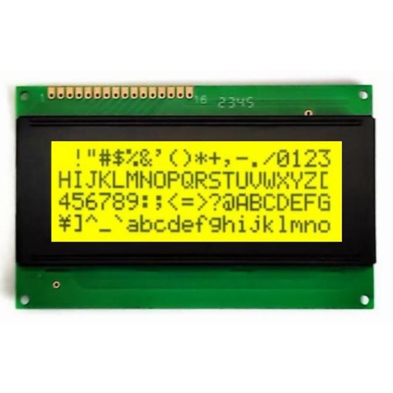
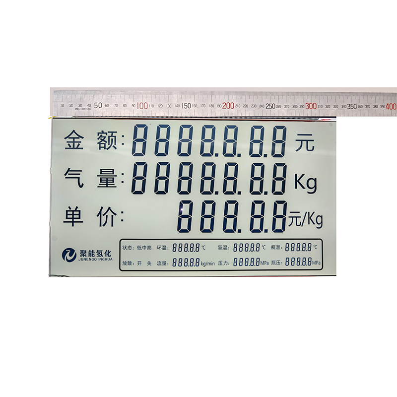
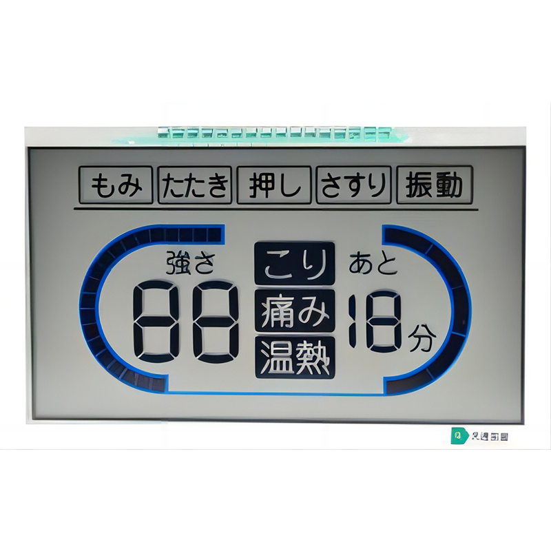
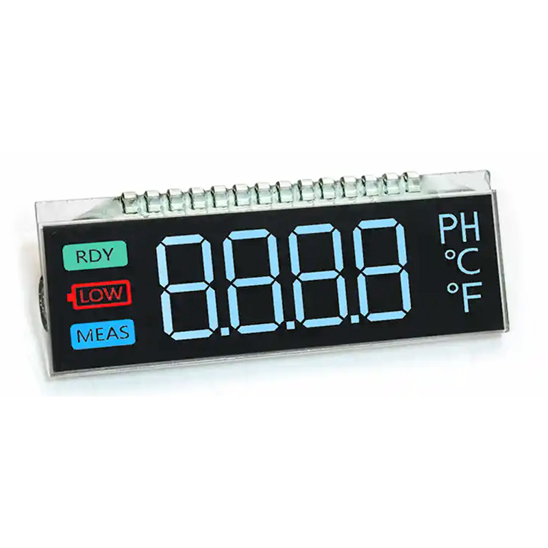
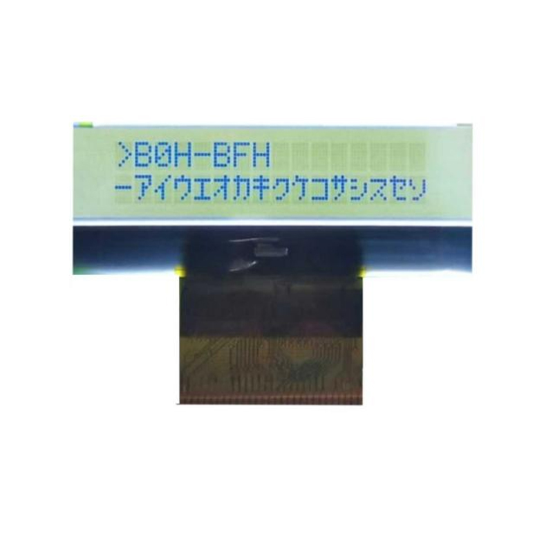
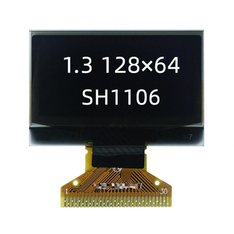
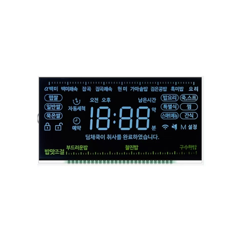
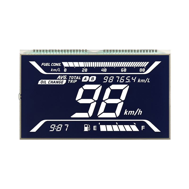
| Connecting an LCD display | ILI9341, ST7735 | Displays graphical information. |
| Reading data from sensors | MPU6050, BMP180 | Acquires sensor data for various applications. |
| Communicating with SD card modules | SD card module | Enables data storage and retrieval. |
| Controlling peripherals like motors and LEDs | Motor drivers, LED drivers | Provides control signals. |
These are just a few examples; the ESP32 SPI interface's capabilities allow for seamless integration with a wide range of peripherals, expanding the possibilities for diverse projects.
For more information on embedded system development and high-quality LCD displays, consider exploring Dalian Eastern Display Co., Ltd. They offer a wide variety of display solutions for various applications.
Troubleshooting SPI communication problems often involves verifying proper wiring, checking the SPI configuration settings on the ESP32, and ensuring compatibility between the ESP32 and the peripheral device. Consult the datasheets of both devices for detailed specifications.
This guide offers a solid foundation for understanding and utilizing the ESP32 SPI interface. By mastering these concepts, you can significantly expand the capabilities of your ESP32-based projects.