Dalian Eastern Display Co., Ltd.
Dalian Eastern Display Co., Ltd.


This guide provides a comprehensive overview of the SPI interface, covering its fundamentals, applications, advantages, disadvantages, and practical considerations. Learn how this versatile serial communication protocol works, its various modes, and how to implement it effectively in your projects. We'll explore real-world examples and offer practical tips for maximizing performance and troubleshooting common issues.
The Serial Peripheral Interface (SPI) is a synchronous, full-duplex, master-slave communication bus widely used for short-distance communication, primarily in embedded systems. Unlike asynchronous protocols like I2C, SPI uses a clock signal to synchronize data transfer, enabling faster data rates. It's a four-wire interface, typically consisting of four lines: MOSI (Master Out Slave In), MISO (Master In Slave Out), SCK (Serial Clock), and SS (Slave Select/Chip Select).
The master device initiates communication by selecting a specific slave device using the SS line. It then transmits data on the MOSI line, synchronized by the SCK clock signal. The slave device receives this data and responds by sending data back on the MISO line, also synchronized by the SCK. The full-duplex nature allows simultaneous data transmission in both directions, enhancing efficiency.
SPI supports different data transfer modes, determined by the clock polarity (CPOL) and clock phase (CPHA). CPOL defines the idle state of the clock signal (high or low), while CPHA defines when data is sampled (on the rising or falling edge of the clock). Understanding these modes is crucial for proper communication.
| Mode | CPOL | CPHA | Description |
|---|---|---|---|
| Mode 0 | 0 | 0 | Idle clock low, data sampled on rising edge |
| Mode 1 | 0 | 1 | Idle clock low, data sampled on falling edge |
| Mode 2 | 1 | 0 | Idle clock high, data sampled on rising edge |
| Mode 3 | 1 | 1 | Idle clock high, data sampled on falling edge |
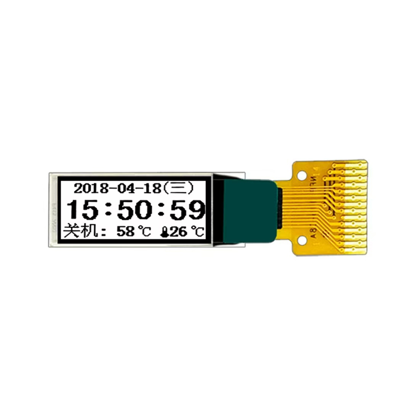
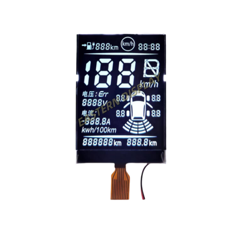
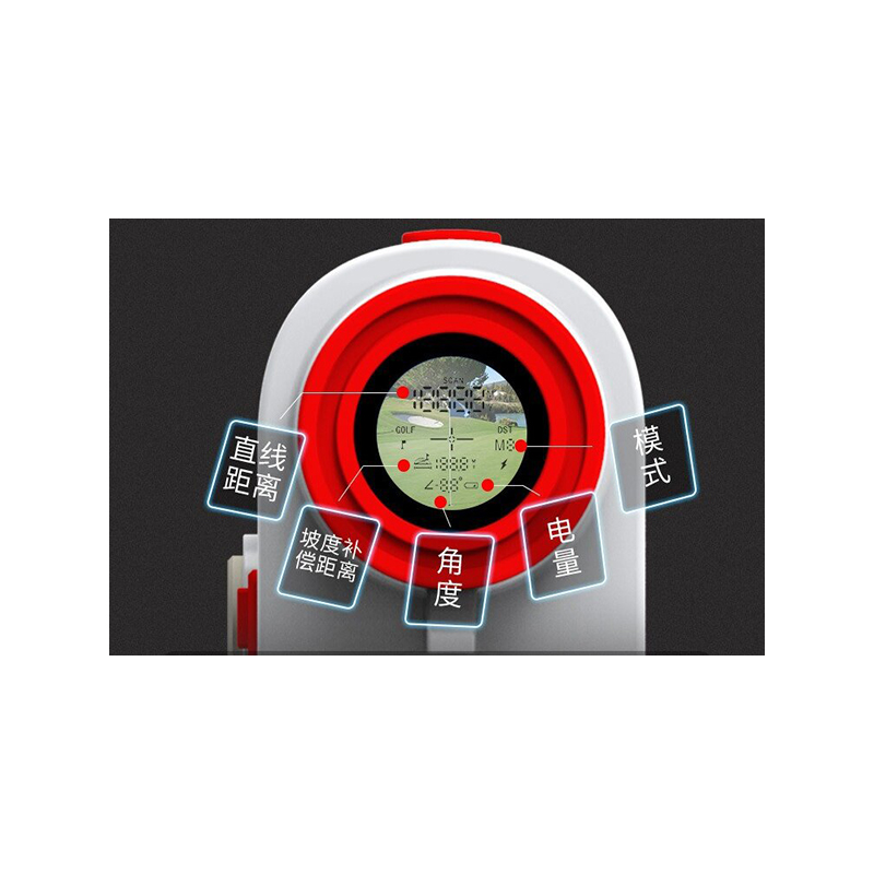
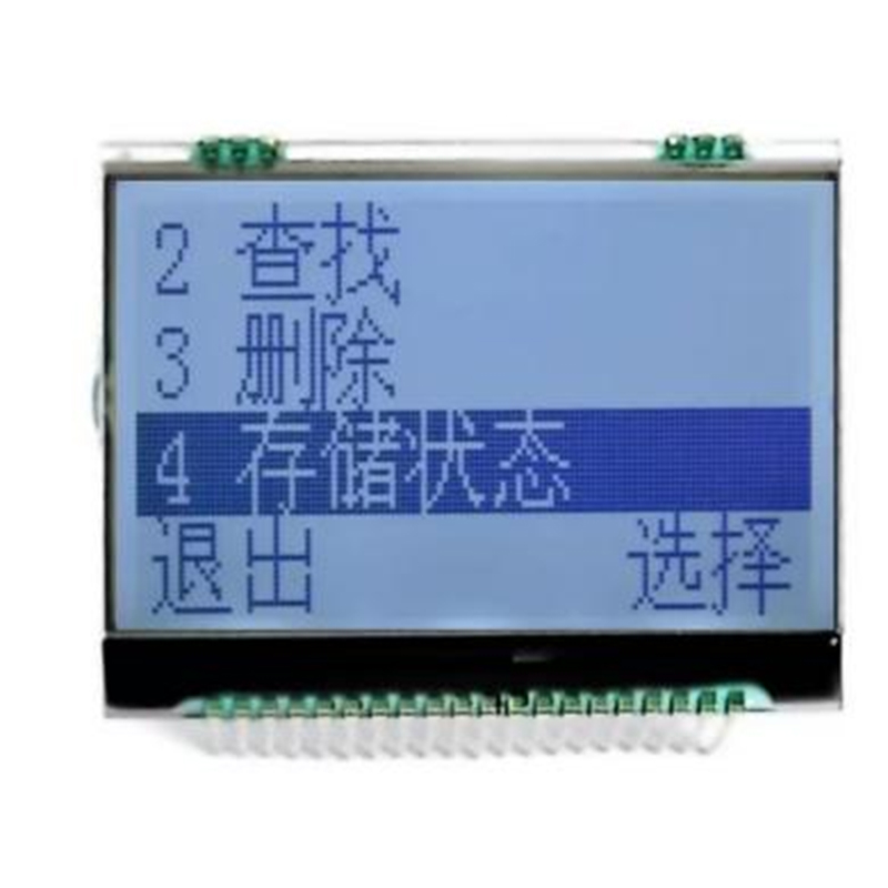
SPI finds applications in various embedded systems, including:
Implementing an SPI interface involves configuring the SPI peripheral on your microcontroller and selecting the appropriate mode and clock speed. The specific implementation details will depend on the microcontroller and the slave device. Many microcontrollers provide libraries and example code to simplify the process.
Common issues in SPI communication include incorrect clock settings, incorrect data transfer mode, and hardware faults. Using a logic analyzer can help identify these problems. Careful examination of the SPI signals (MOSI, MISO, SCK, SS) can pinpoint the source of the error.
This guide provides a foundational understanding of the SPI interface. For more in-depth information, refer to the datasheets of your specific microcontroller and slave devices. Remember to always consult the manufacturer's documentation for detailed specifications and best practices.