Dalian Eastern Display Co., Ltd.
Dalian Eastern Display Co., Ltd.


The Arduino Mega 2560 boasts a robust SPI (Serial Peripheral Interface) bus, a versatile and efficient communication protocol ideal for connecting various peripherals like sensors, displays, and memory chips. This guide will walk you through the fundamentals of SPI interface Arduino Mega 2560 communication, covering everything from basic setup to advanced techniques. We'll focus on practical applications and provide examples to help you integrate SPI devices smoothly into your projects.
SPI is a synchronous, full-duplex communication protocol. This means that data transmission occurs simultaneously in both directions, significantly improving efficiency compared to asynchronous methods. Key characteristics include:
The Arduino Mega 2560 provides the following pins for SPI communication:
While these are the default pins, you can remap them if necessary within the Arduino IDE.
The Arduino IDE includes a built-in SPI library that simplifies SPI interface Arduino Mega 2560 communication. To use it, you'll need to include the library in your code:
#include <SPI.h>Before initiating communication, ensure the SPI interface is properly configured. This typically involves setting the clock speed and data order. The following code snippet demonstrates basic configuration:
SPI.begin(); // Initialize SPISPI.beginTransaction(SPISettings(1000000, MSBFIRST, SPI_MODE0)); // Set clock speed to 1MHz, MSB first, mode 0Adjust the clock speed (1000000 in this example) based on the requirements of your connected slave device. Consult the device's datasheet for optimal settings.
Once the SPI interface is configured, you can communicate with your slave devices. This usually involves sending commands and receiving data. The following demonstrates a simple example of sending data to and receiving data from a slave device:
byte dataToSend = 0x55;byte dataReceived = SPI.transfer(dataToSend); This code sends the byte 0x55 and receives a byte from the slave device. The `SPI.transfer()` function handles the low-level SPI communication.
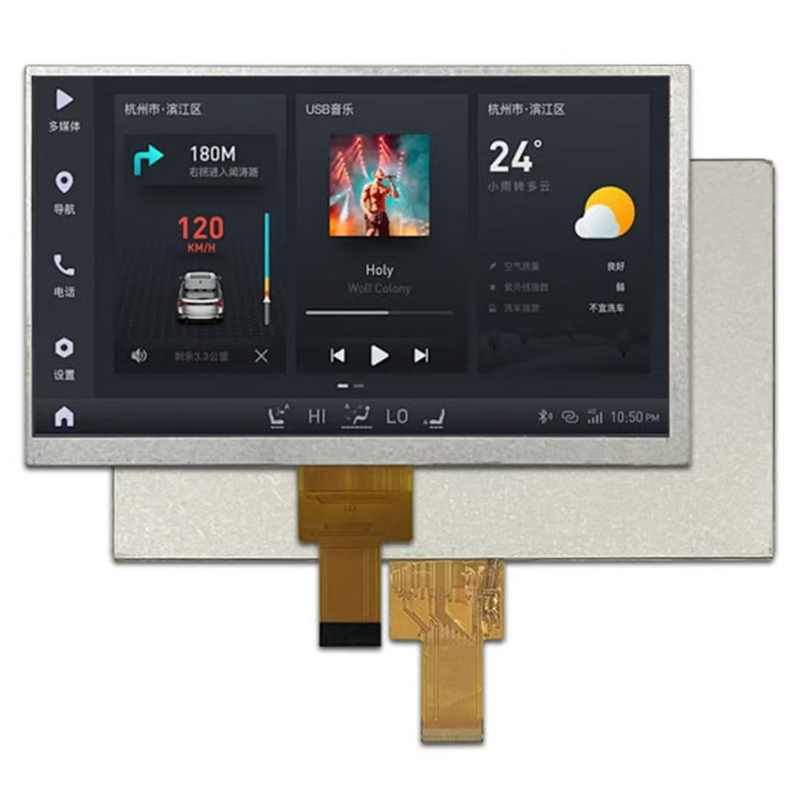
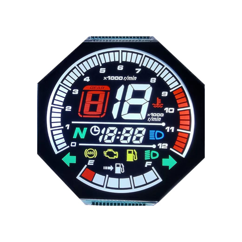
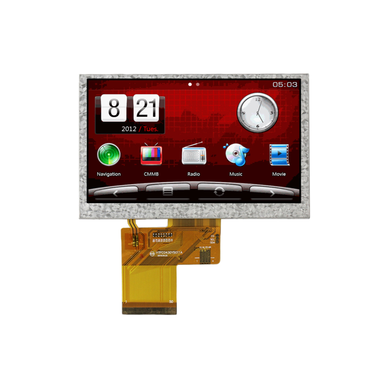
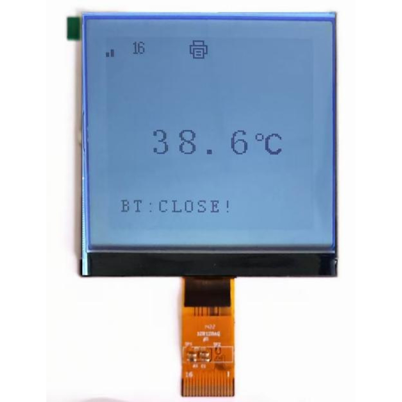
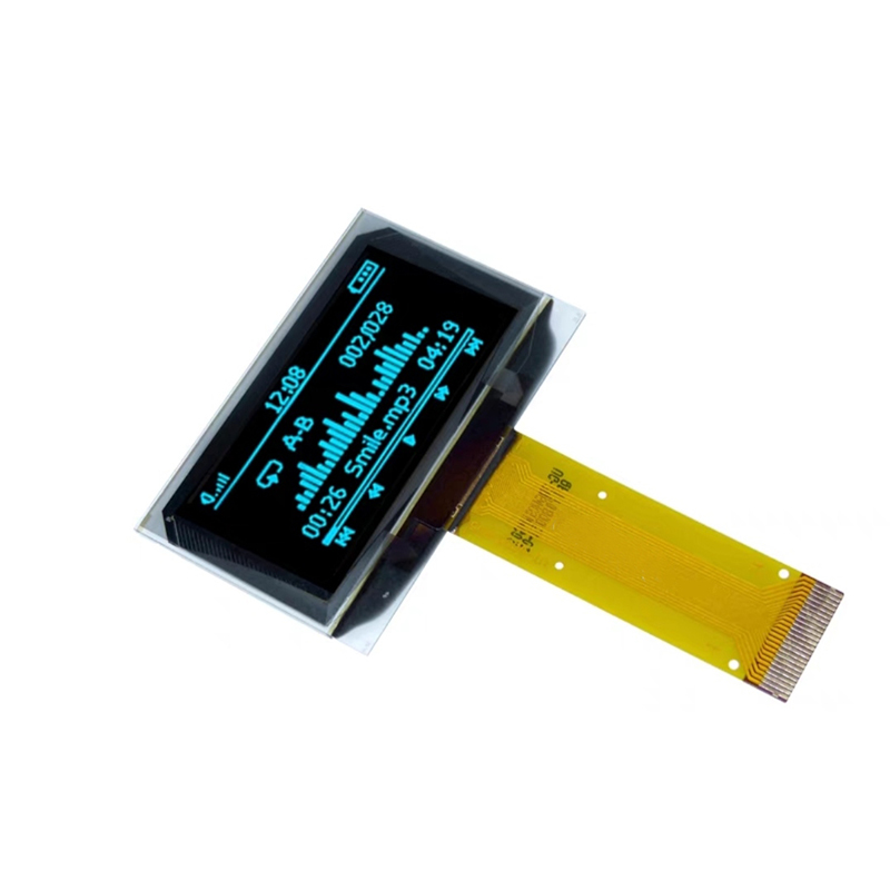
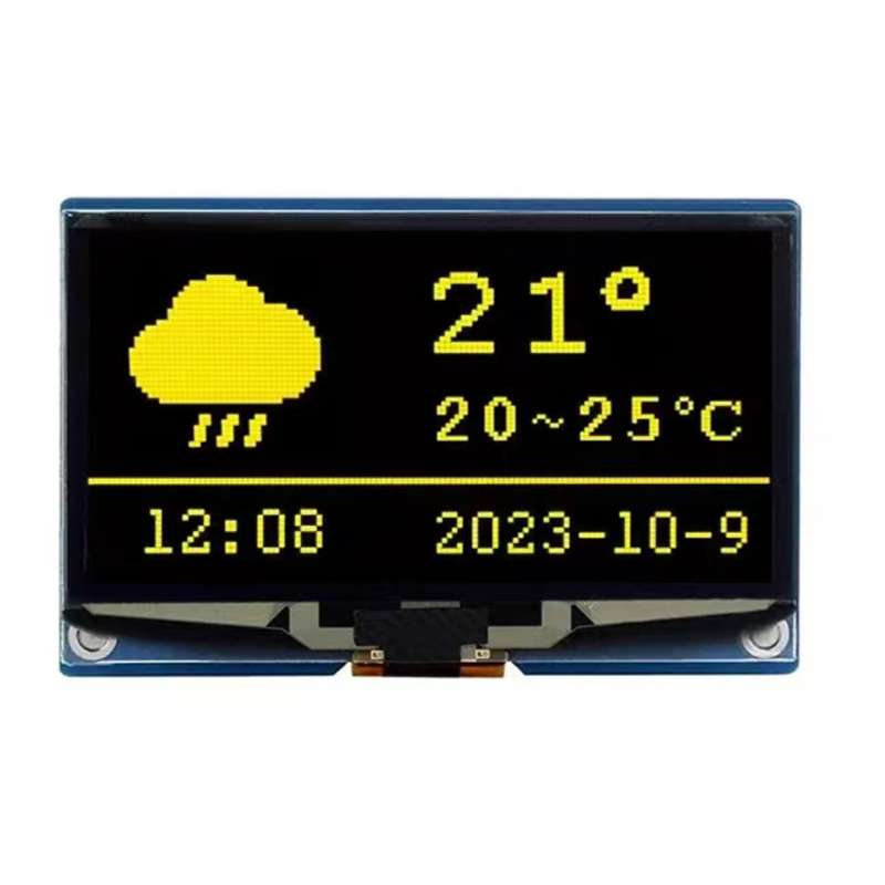
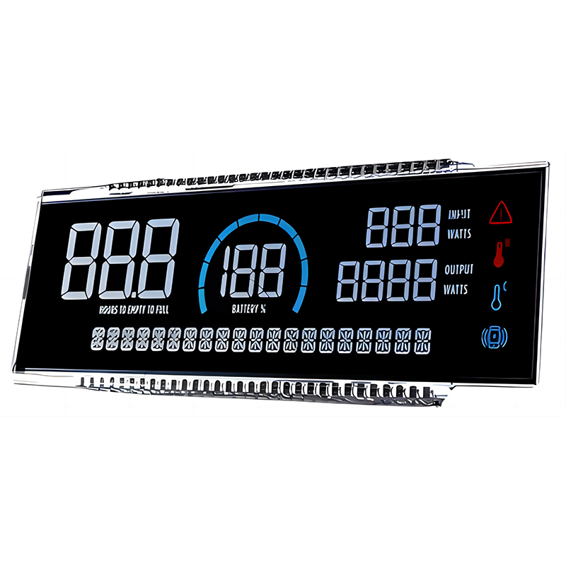
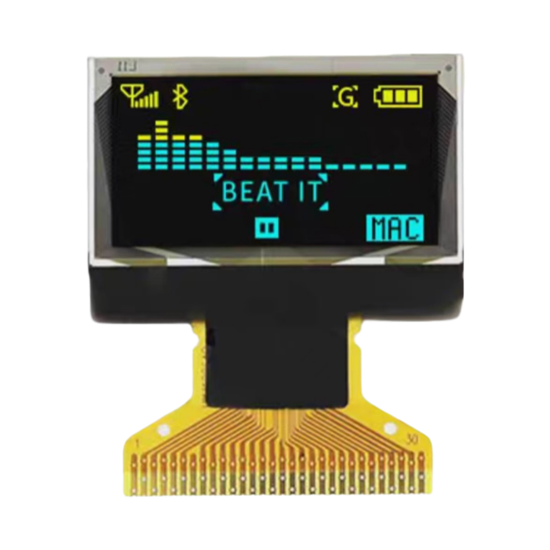
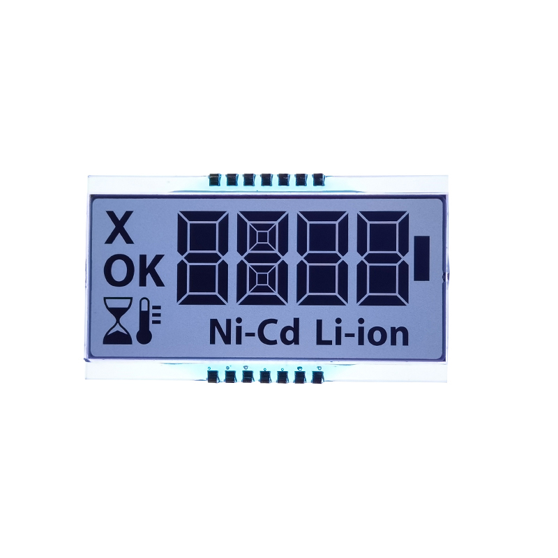
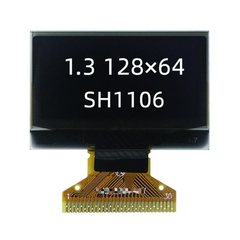
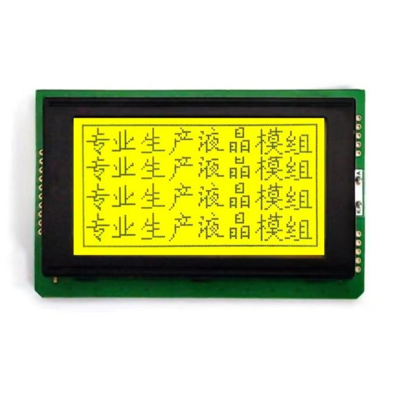
Many LCD displays utilize the SPI interface. Let's say you're using a specific LCD display like the ST7735. You'll need to refer to its datasheet for precise pin connections and command sequences. The datasheet will guide you on how to initialize the display and send commands to control its functionality. Remember to use the appropriate library for your particular LCD model. Libraries such as Adafruit_ST7735 significantly simplify the process.
Problems with SPI interface Arduino Mega 2560 can stem from various sources. Here are a few common issues and troubleshooting steps:
For more advanced applications, consider exploring interrupt-driven SPI communication for improved efficiency and real-time responsiveness. Also, understanding the different SPI modes (SPI_MODE0, SPI_MODE1, SPI_MODE2, SPI_MODE3) and their implications will allow you to optimize your communication based on your specific hardware requirements.
Remember to consult the datasheets of your specific SPI devices for detailed information regarding their operation and communication protocols. This guide provides a general framework, but the specifics will vary depending on the peripherals you are using. For further resources and support, explore the Arduino community forums and documentation.
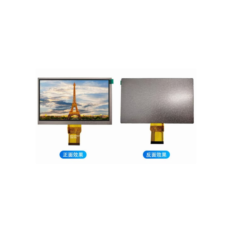
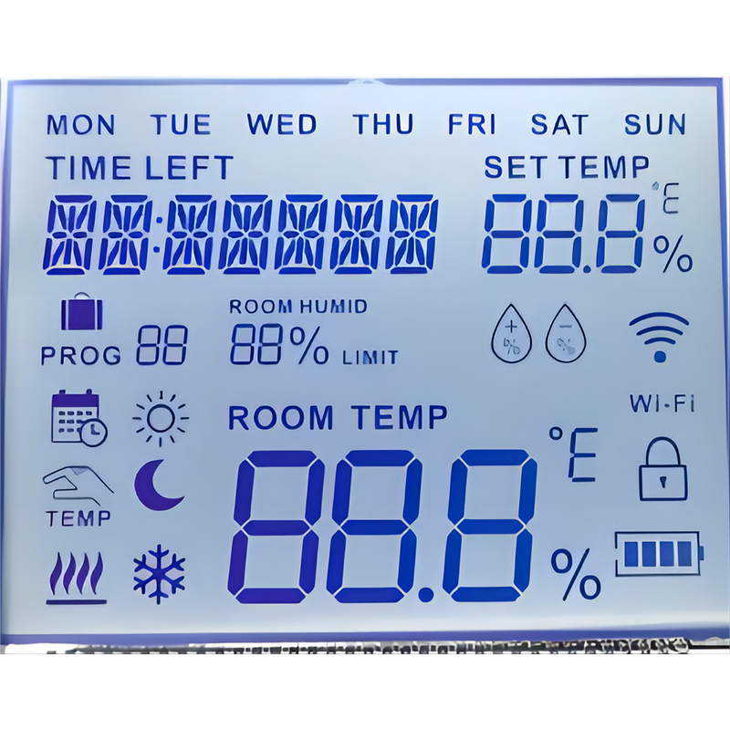
For high-quality LCD displays for your projects, consider exploring the range of options available from Dalian Eastern Display Co., Ltd. They offer a wide selection of displays with varying specifications to meet diverse application needs.