Dalian Eastern Display Co., Ltd.
Dalian Eastern Display Co., Ltd.


This comprehensive guide explores the intricacies of the SPI interface STM32, covering everything from fundamental concepts to advanced techniques. Learn how to configure, utilize, and troubleshoot SPI communication on your STM32 microcontroller, including practical examples and code snippets. We'll delve into various aspects, ensuring you gain a thorough understanding and the ability to seamlessly integrate SPI peripherals into your projects.
The Serial Peripheral Interface (SPI) is a synchronous, full-duplex communication bus commonly used for short-distance communication, primarily between a microcontroller and peripheral devices. Its popularity stems from its simplicity, speed, and relatively low hardware overhead. Understanding the SPI interface STM32 involves grasping key concepts like MOSI (Master Out Slave In), MISO (Master In Slave Out), SCK (Serial Clock), and SS (Slave Select).
Proper configuration of clock polarity (CPOL) and clock phase (CPHA) is crucial for successful SPI interface STM32 communication. These settings define how data is sampled on the clock edge. Incorrect settings will lead to communication errors. The STM32CubeMX configuration tool simplifies this process, allowing you to visually select the appropriate values.
The STM32CubeMX tool provides a user-friendly interface for configuring peripherals, including the SPI bus. By selecting the appropriate SPI pins, setting the clock speed, data order, and other parameters, you can quickly generate the necessary initialization code. This significantly reduces development time and eliminates potential configuration errors. You'll find detailed documentation on their website.
The STM32 HAL (Hardware Abstraction Layer) libraries offer a high-level interface for interacting with peripherals. We'll demonstrate how to use the HAL functions to efficiently write and read data over the SPI interface STM32. Examples will illustrate how to initialize the SPI, transmit and receive data, and handle potential errors. This ensures code portability and maintainability.
Let’s consider a practical example: communicating with an accelerometer using the SPI interface STM32. We will outline the steps involved, from setting up the communication parameters to reading and interpreting the sensor data. Specific sensor models may vary in their register map and data formats; always refer to the manufacturer’s datasheet.
For high-throughput applications, Direct Memory Access (DMA) offers significant performance improvements. Using DMA with the SPI interface STM32 allows for asynchronous data transfer, freeing up the CPU for other tasks. We will explore how to configure DMA for SPI communication to optimize data transfer speeds.
Understanding and handling potential errors is crucial for robust SPI interface STM32 applications. We will discuss common error scenarios and how to utilize interrupts for efficient error handling and improved system responsiveness. Examples include timeout errors and communication inconsistencies.
| Mode | CPOL | CPHA | Data Sampling |
|---|---|---|---|
| Mode 0 | 0 | 0 | Leading edge |
| Mode 1 | 0 | 1 | Trailing edge |
| Mode 2 | 1 | 0 | Leading edge |
| Mode 3 | 1 | 1 | Trailing edge |
For more information on STM32 microcontrollers and their peripherals, you might find the resources at STMicroelectronics helpful.
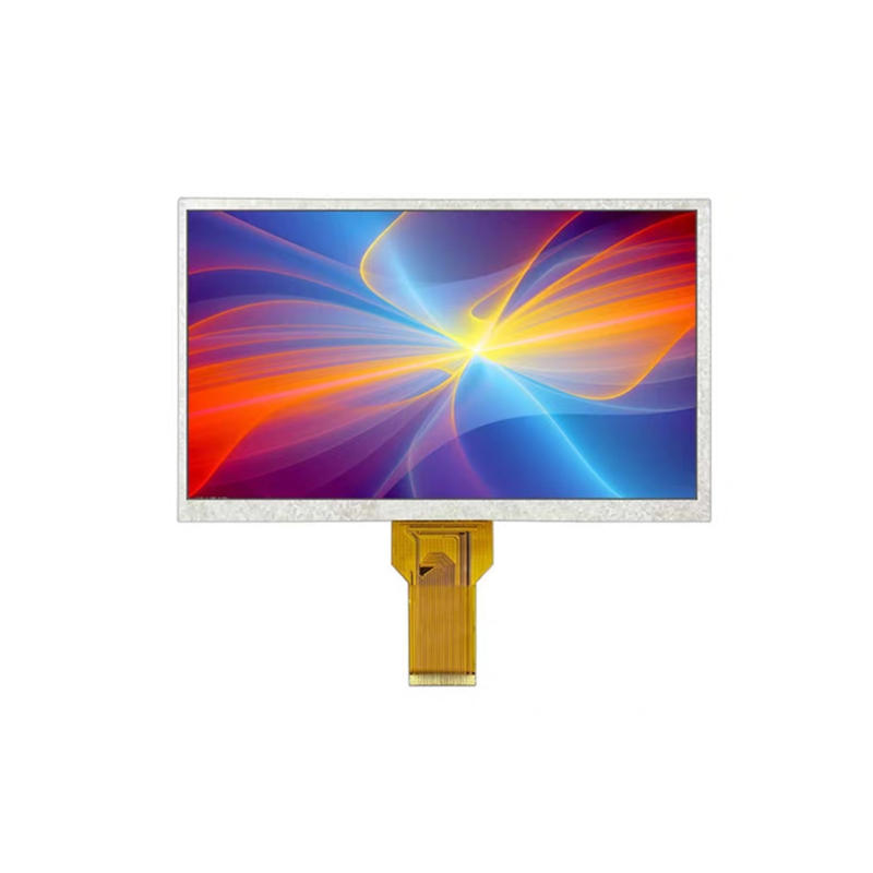
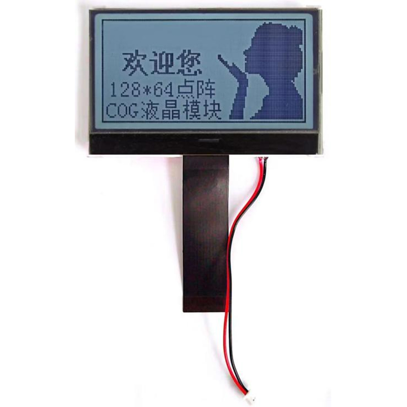
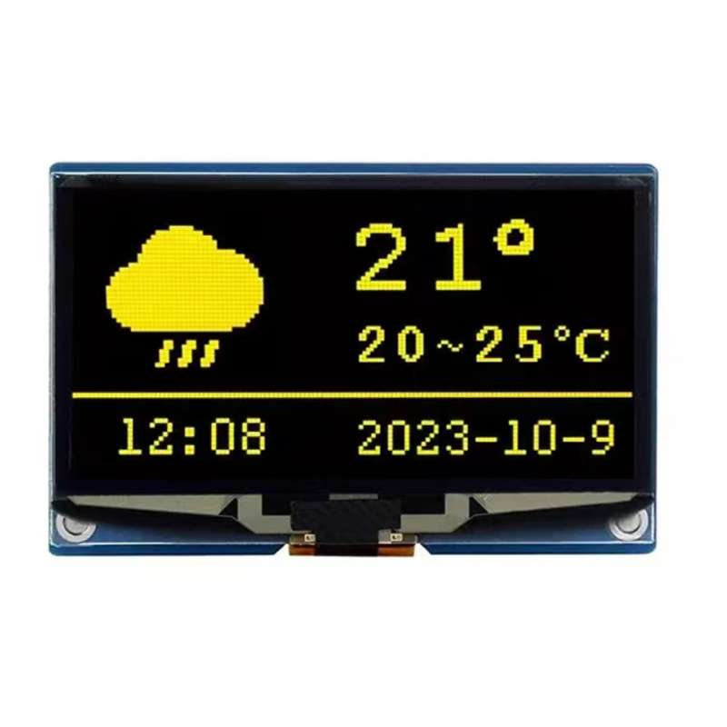
Need high-quality LCD displays for your embedded projects? Explore the range of options available at Dalian Eastern Display Co., Ltd.