Dalian Eastern Display Co., Ltd.
Dalian Eastern Display Co., Ltd.


This guide provides a detailed walkthrough of integrating SPI TFT displays with Arduino, covering everything from choosing the right display to troubleshooting common issues. Learn about different display types, essential libraries, wiring diagrams, and practical coding examples. Discover how to leverage this powerful combination for a wide array of projects.
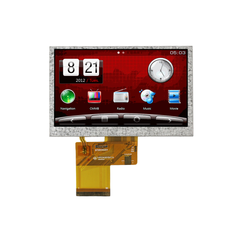
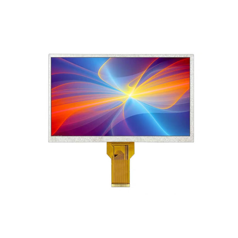
An SPI TFT (Thin Film Transistor) display is a color LCD screen that uses the Serial Peripheral Interface (SPI) protocol for communication with a microcontroller like the Arduino. SPI is a synchronous, full-duplex communication protocol known for its speed and efficiency, making it ideal for high-resolution displays that require fast refresh rates. Unlike parallel interfaces, SPI requires fewer data pins, simplifying wiring and leaving more GPIO pins available for other components in your project.
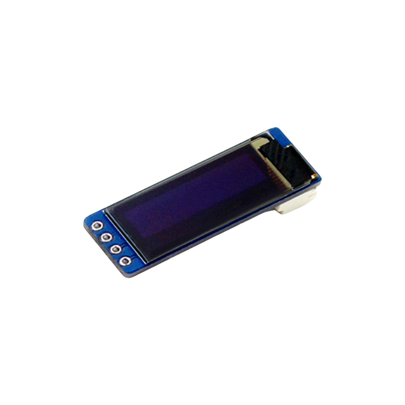
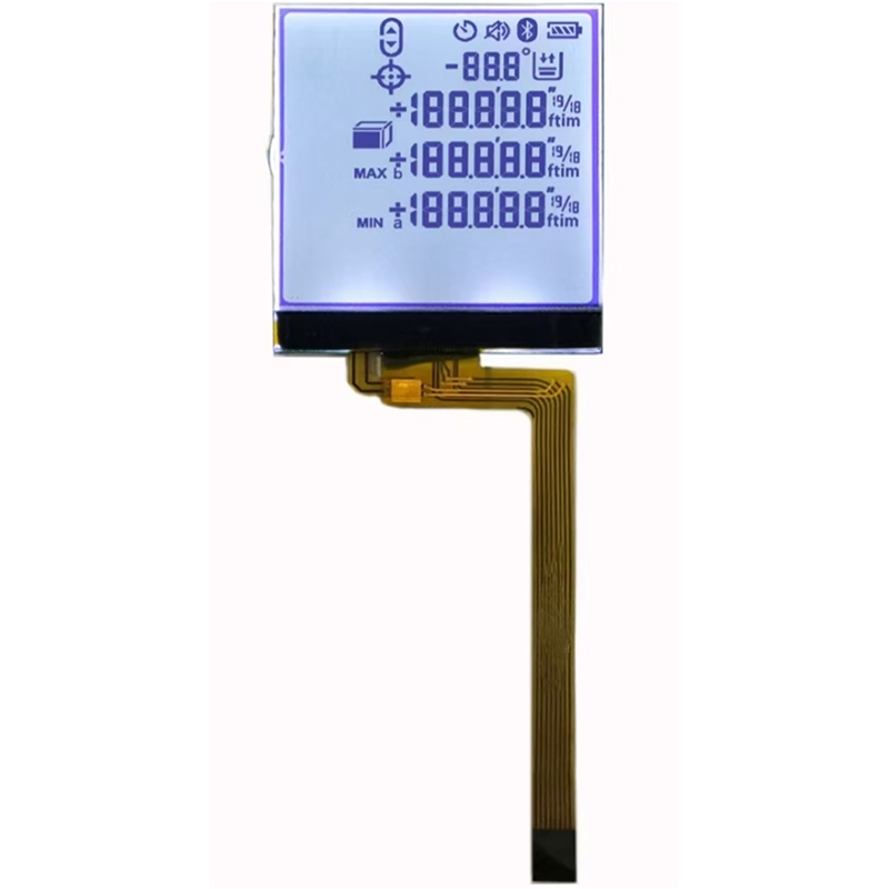
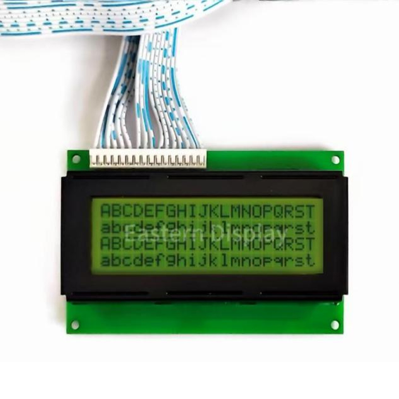
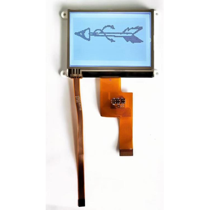
Selecting the appropriate SPI TFT display for your Arduino project depends on several factors: resolution (e.g., 128x128, 240x320, 320x480), color depth (e.g., 16-bit, 18-bit), display size, and interface type (ensuring it’s SPI). Consider your project's requirements and budget when making your choice. Many suppliers offer a wide variety of options.
Besides your Arduino board and chosen SPI TFT display, you'll need connecting wires, a breadboard (optional, but highly recommended), and potentially a level shifter if the display's voltage requirements differ from the Arduino's 5V output. Always consult the display's datasheet for the precise pinout and voltage specifications.
A typical wiring diagram involves connecting the following pins: VCC (power), GND (ground), CS (chip select), MOSI (master out slave in), MISO (master in slave out), SCK (clock), and potentially other control pins (reset, data/command). Detailed wiring diagrams are usually provided in the display's documentation. Refer to your specific display's datasheet for precise pin assignments.

You'll need an appropriate library to control your SPI TFT display from your Arduino. Popular libraries include Adafruit_GFX and specific libraries for particular display models. Install the necessary library through the Arduino IDE's Library Manager.
The following code snippet demonstrates a basic example using the Adafruit_TFTLCD library. Remember to adjust pin definitions according to your specific wiring. Always refer to the documentation for the chosen library for more advanced functionalities.
#include // ... Pin definitions ...Adafruit_TFTLCD tft(LCD_CS, LCD_CD, LCD_WR, LCD_RD, LCD_RESET);void setup() { tft.begin(0x9341); // Replace with your display's ID tft.fillScreen(ST7735_BLACK); tft.setCursor(0, 0); tft.setTextColor(ST7735_WHITE); tft.setTextSize(2); tft.println(Hello, SPI TFT!);}void loop() { // ... Your code here ...} Check the wiring, power supply, and the library installation. Ensure the correct display ID is used in your code.
This can be caused by incorrect wiring, improper library configuration, or power supply issues.
Check your SPI settings and ensure they are optimized for your display.
For high-quality SPI TFT displays and excellent customer support, consider exploring reputable suppliers like Dalian Eastern Display Co., Ltd.. They offer a wide range of display options to suit various project needs. Their commitment to quality ensures a seamless integration experience with your Arduino projects. Remember to always cross-reference datasheets and specifications from the manufacturer before finalizing your purchase.
| Display Feature | Option A | Option B |
|---|---|---|
| Resolution | 320x240 | 240x135 |
| Color Depth | 16-bit | 18-bit |
| Interface | SPI | SPI |
This information is for guidance only. Always refer to the official documentation for your specific SPI TFT display and Arduino model.